EasyManua.ls Logo

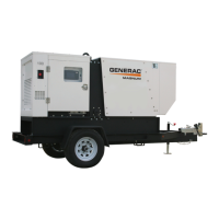
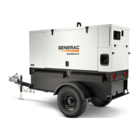
Generac Power Systems MAGNUM MMG75D

Generac Power Systems MAGNUM MMG75D
68 pages
To Next Page IconTo Next Page
Loading...
OPERATING MANUAL
Parts manuals available online at www.generacmobile.com
33701 C 02/16
01886
DIESEL GENERATOR
With Controller
TM
MMG75D • MMG100D

Table of Contents

Other manuals for Generac Power Systems MAGNUM MMG75D

Questions and Answers:

Generac Power Systems MAGNUM MMG75D Specifications

General IconGeneral
ModelMMG75D
TypePortable Generator
Fuel TypeDiesel
Starting SystemElectric Start
Voltage120/240 V
Frequency60 Hz
Outlets4 x 120V 20A
Wheel KitIncluded
Engine Type4-Cycle

Summary

Section 1 - Safety

Safety Notes

Explains the safety alert symbol and the meaning of DANGERS, WARNINGS, CAUTIONS, NOTICES, and NOTES.

Operating Safety

Details safe operating practices, including unit placement, environmental conditions, and operator awareness.

Engine Safety

Covers hazards associated with internal combustion engines and essential safety precautions.

Service Safety

Outlines safety guidelines for qualified personnel performing service or maintenance on the unit.

Towing Safety

Provides essential guidelines for safely towing the generator unit, including hitch and trailer checks.

Safety Symbol Summary

Explains the meaning of various safety and operating decals used on the unit for hazard identification.

Section 2 - General Information

Specifications

Details technical specifications for the MMG75D and MMG100D generator models, including engine and generator data.

Power Zone Gen Controller

Details the auto start controller, its functions, features like the Home button, and its interface for monitoring and control.

Engine Button

Explains the Engine screen on the controller, displaying oil pressure, coolant temperature, and battery voltage.

Generator Button

Details the Generator screen, showing voltage, frequency, amps, and winding configuration.

Engine Tab

Provides detailed engine maintenance and instrumentation data, including alarms and gauge readings.

Generator Tab

Presents generator maintenance and instrumentation data, including analog meters and bar graphs.

Alarms Tab

Displays warnings, trips, shutdowns, DTCs, and event logs. Includes Table 1: Diagnostic Trouble Codes.

Diesel Exhaust Filter Monitoring

Explains indicators and status pages related to the Diesel Particulate Filter (DPF) system.

Controller Information Displays, Functions, and Reset

Explains how the controller displays information, handles faults, and can be reset.

Section 3 - Operation

Prestart Checklist

Lists essential checks to be completed before starting the unit, applicable to manual and remote starts.

Manually Starting the Unit

Step-by-step instructions for starting the generator in Manual mode using the control panel.

Auto (Remote) Starting the Unit

Explains how to set up and use the unit for automatic starting via a transfer switch or remote signal.

Transfer Switch

Discusses the function and installation requirements of a transfer switch for standby power applications.

Generator Output Connections

Details how to connect external loads to the generator using connection lugs, emphasizing safety.

Fine Voltage Adjustment

Describes the process of adjusting generator output voltage using the Voltage Adjust screen.

Voltage Selector Switch

Explains the function and operation of the voltage selector switch for choosing output voltage configurations.

Exhaust Filter Cleaning Operations

Covers automatic and manual exhaust filter cleaning (regeneration) and safety precautions.

Emergency Stop Switch

Explains the location, activation, and function of the emergency stop switch.

Section 4 - Maintenance

General Maintenance

Covers essential safety precautions and general maintenance tasks for reliable operation.

Basic Maintenance Schedule

Provides a schedule of recommended maintenance intervals for various components and systems.

Section 5 - Troubleshooting

General Troubleshooting

Provides a guide for identifying and resolving common problems with the generator unit.

Section 6 - Wiring Diagrams

Related product manuals