Operation
28 MMG75D-100D Operating Manual 33701 C
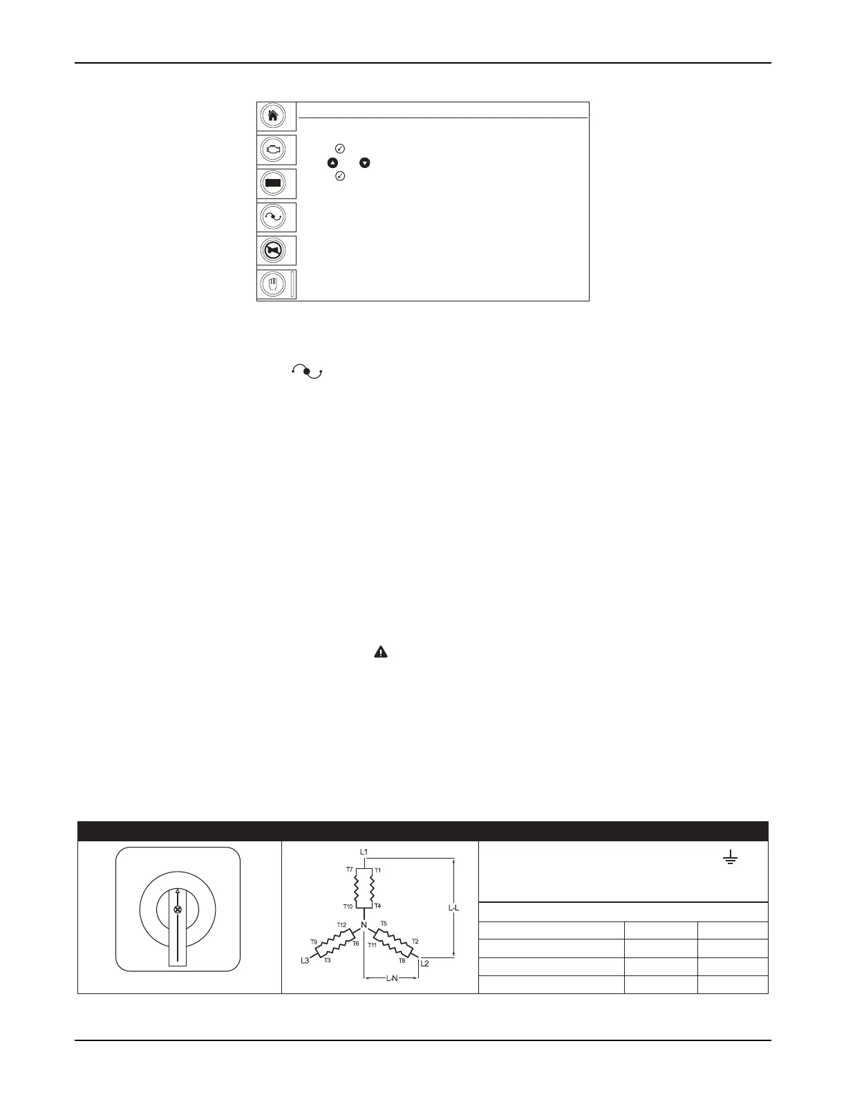
Figure 3-6. Voltage Adjust Screen
1. With the unit running, press .
2. Press . The voltages displayed will begin flashing.
3. Use ▲ and ▼ to adjust the voltage.
4. Press to confirm the new voltage. The voltages displayed will stop flashing.
VOLTAGE SELECTOR SWITCH
The voltage selector switch mechanically changes the connections between the generator output leads and the
connection lugs on the main control panel. Voltage ranges are selected by rotating the handle on the switch to the
desired voltage.
WARNING
Electric Shock. Never change the voltage selector switch while the engine is running
or the controller is on. If the engine is running or starts while the setting is being
changed, severe arcing will occur, resulting in death, serious injury or damage to the
switch and generator windings.
The voltage selector switch is equipped with a lockout mechanism. Once the proper voltage has been selected,
insert a padlock through the lockout hole(s). By locking the handle in place, unauthorized changing of the voltage
setting is prevented.
00396
Manual Mode
GEN
V
+
-
Voltage Adjust
- Press , voltage will begin flashing
- Use and arrows to adjust voltage
- Press to confirm new voltage. Numbers will stop flashing
L-N Average
L-L Average
480
277
V
+
-
L1-L2 = 208V L1-N = 120V N =
L2-L3 = 208V L2-N = 120V
L3-L1 = 208V L3-N = 120V
VOLTAGES AT RECEPTACLES
120/208V 3-PHASE
Switch styles vary by model.
RECEPTACLE L-L L-N
GFCI - 120V
GFCI w/Buck - 120V
Twist-locks 208V 120V
277/
480V
120/
208V
120/
240V
00085
 Loading...