Do you have a question about the Generac Power Systems NP45G Series and is the answer not in the manual?
Detailed power output, voltage, and current ratings for all generator models.
Covers engine type, cooling, horsepower, displacement, and starter details.
Lists torque values for various engine components for proper assembly.
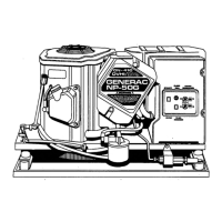
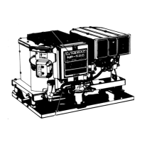
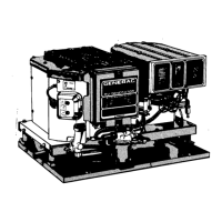
Provides a visual overview and physical characteristics of the generator unit.
Identifies and labels key components of the generator set.
Details safety shutdown systems like low oil pressure and high temperature.
Outlines safety standards and general requirements for vehicle installation.
Describes mounting the generator within a dedicated vehicle compartment.
Details suspending the generator below the vehicle chassis for mounting.
Illustrates side and bottom exhaust system types for different mounting.
Explains how to reconfigure the generator for dual voltage output.
Covers generator interconnections when using a double pole, double throw transfer switch.
Details installation using an isolation type receptacle for power connection.
Specifies recommended battery types and cable sizes for optimal performance.
Outlines the necessity of grounding exposed non-current carrying parts.
Describes available remote panels for starting and stopping the generator.
Lists essential pre-operation checks for installation and engine preparation.
Identifies key controls like start/stop switch and circuit breakers on the panel.
Step-by-step guide to safely start the generator engine and supply power.
Procedure for properly shutting down the generator engine and power output.
Instructions for adjusting the idle mixture screw on the carburetor.
Details adjustment procedures for the choke solenoid and heater assembly.
Covers setting spark plug gap and ignition module air gap for optimal ignition.
Procedure for checking and adjusting valve clearance for proper engine operation.
Instructions on adjusting the generator drive belt tension correctly.
Guide to adjusting the engine governor for correct frequency and speed.
Analyzes the DC circuit state when the engine is not running.
Explains the DC circuit behavior during engine cranking.
Details the DC circuit operation after the engine starts and is running.
Describes the DC circuit state during a normal engine shutdown.
Explains the initial voltage buildup and magnetism process during startup.
Details how the generator performs under connected electrical loads.
Flow chart for diagnosing why the engine fails to crank.
Flow chart for troubleshooting engines that crank but do not start.
Flow chart for diagnosing why the engine shuts down after release of the start/stop switch.
Flow chart to address engines that start with difficulty or run unevenly.
Flow chart to diagnose issues preventing engine shutdown.
Flow chart for troubleshooting low or absent AC power output.
Procedure to inspect and test the 15 amp DC control circuit fuse.
Instructions for testing battery terminals, cables, charge, and condition.
Detailed steps to test the starter contactor for proper operation.
Procedure to test the starter motor's cranking ability.
Method to verify the functionality of the start/stop switch.
Steps to test the operation of Control Relay CR1.
Verifies adequate fuel supply is available for generator operation.
Ensures fuel shutoff valves in the supply line are open.
Checks for proper fuel flow to the carburetor inlet.
Tests the fuel pump's operation and voltage supply.
Checks for ignition spark and inspects spark plugs and ignition components.
Tests the diode, field boost diode, and resistor within the choke module.
Observes automatic choke operation during engine cranking.
Assesses engine mechanical condition and compression for proper running.
Tests the continuity and operation of Control Relay CR2.
Checks engine oil level to prevent shutdown due to low pressure.
Tests the oil pressure switch for continuity and response to pressure.
Tests the oil temperature switch for continuity and response to temperature.
Tests the resistance value of Resistor R1 for proper function.
Verifies the functionality of the generator's AC output line circuit breakers.
Inspects vehicle wiring for defects if output is good but loads don't receive power.
Measures generator AC output voltage and frequency at no-load.
Evaluates voltage and frequency under various electrical load conditions.
Guides adjustment of the engine governor for optimal speed and frequency.
Measures resistance of the stator DPE windings for shorts or opens.
Checks resistance of stator power windings for integrity.
Tests rotor circuit wiring, brushes, brush holders, and slip rings for issues.
Verifies the sensing wires between the regulator and stator for continuity.
Adjusts the voltage regulator potentiometer to achieve correct output voltage.
| Engine Displacement | 224 cc |
|---|---|
| Starting System | Recoil |
| Voltage | 120/240 V |
| Frequency | 60 Hz |
| Rated Watts | 4500 W |
| Fuel Type | Gasoline |
| Engine | Generac OHV |
| Outlets | 2 x 120V 20A (5-20R), 1 x 120/240V 30A (L14-30R) |
| Running Watts | 4500 |
| Outlet Types | 5-20R, L14-30R |