600-1152A 13
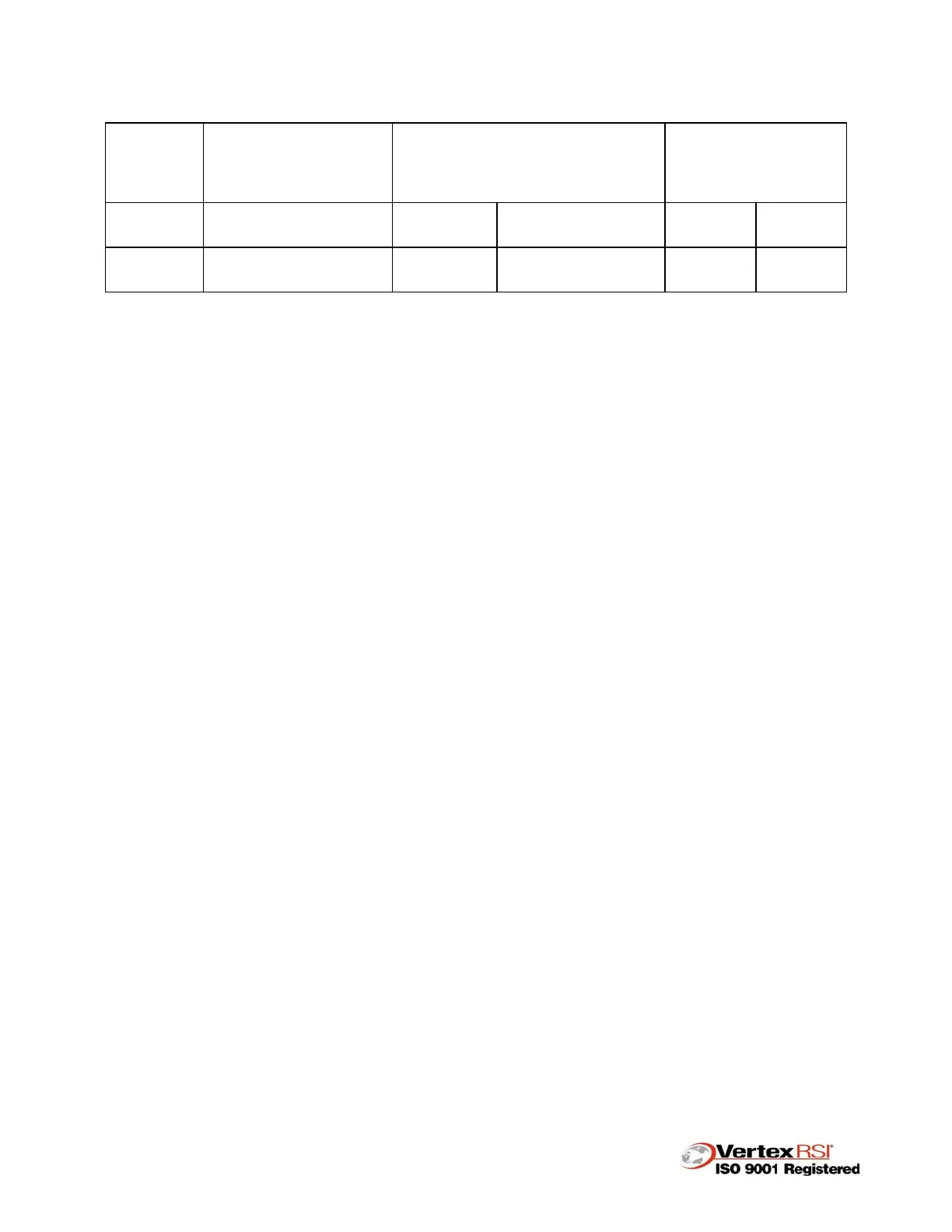
Table 3. Jack Grease Chart
JACK
SIZE
APPLICATION
GREASE CAPACITY
SHOTS WEIGHT
*RELUBRICATION
AMOUNT
SHOTS
WEIGHT
35 TON 11M Elevation
140
SHOTS
70 Oz. or 4# 6 Oz.
10
SHOTS
5 Oz.
75 TON 11M Azimuth
400
SHOTS
200 Oz. or 12# 8
Oz.
15
SHOTS
7.5 Oz.
* Each grease fitting
3.10 Lightning Protection
The elevation and azimuth axis bearings are protected by looping ground cables from
reflector to pedestal and from pedestal to perimeter ground.
Lightning rods are provided on the top radial beam and reflector apex.
As an option, “down conductors” can be attached to the lightning rods to serve as down
conductors and are attached to the ground field via a lug on the lower azimuth pintle.
The lightning rods and ground cables must be checked periodically to insure continuity
of conductance (good metal to metal contact) to prevent damage to bearings during
electrical storms.
3.11 Rod End Anti-Rotation Screw Adjustment
The anti-rotation setscrews in the jack rod ends of the antenna should be checked and
adjusted during routine maintenance every three months or as necessary. Each rod end
has two (2) tapped holes in a circular pattern around the pin connecting the jack to the
pedestal or reflector. Each hole contains a setscrew which is adjusted to minimize the
tendency of the jack screw to rotate when the jack is extended or retracted. Figure 2
shows a typical anti-rotation setscrew location.