Do you have a question about the General AOHG18LAC2 and is the answer not in the manual?
Electrical, compressor, and refrigerant specifications for outdoor units.
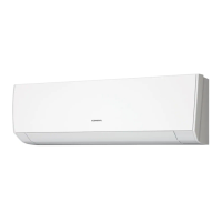
Electrical, fan motor, airflow, and noise level for compact wall-mounted units.
Electrical, fan motor, airflow, and noise level for compact cassette units.
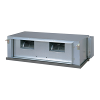
Electrical, fan motor, airflow, and noise level for slim duct and wall-mounted units.
Visual representation and measurements of the outdoor unit.
Dimensional drawings for various compact wall-mounted indoor units.
Dimensional drawings for compact cassette and floor indoor units.
Dimensional drawings for slim duct indoor units.
Diagram illustrating the refrigerant flow and components.
Wiring schematic for the outdoor unit controller PCB assembly.
Wiring schematic for compact wall-mounted indoor units.
Wiring schematic for compact cassette indoor units.
Wiring schematics for floor and slim duct indoor units.
Detailed circuit diagram for the outdoor unit's inverter assembly.
Schematic of the controller PCB assembly for outdoor units.
Schematic of the controller PCB assembly for outdoor units.
Detailed schematic of the outdoor unit controller PCB assembly.
Circuit diagram for the indoor unit's compact wall-mounted control unit.
Schematic of the main PCB for compact wall-mounted indoor units.
Schematic of the indicator PCB for compact wall-mounted indoor units.
Schematic for the optional communication kit and PCB.
Circuit diagrams for compact wall-mounted indoor units.
Detailed schematic of the main PCB for compact wall-mounted indoor units.
Detailed schematic of the indicator PCB for compact wall-mounted indoor units.
Detailed schematic for the optional communication kit and PCB.
Circuit diagrams for compact wall-mounted indoor units.
Detailed schematic of the main PCB for compact wall-mounted indoor units.
Detailed schematic of the indicator PCB for compact wall-mounted indoor units.
Detailed schematic for the optional communication kit and PCB.
Circuit diagrams for compact cassette indoor units.
Detailed schematic of the main PCB for compact cassette indoor units.
Schematic of the power supply PCB for compact cassette indoor units.
Detailed schematic of the indicator PCB for compact cassette indoor units.
Circuit diagrams for floor indoor units.
Detailed schematic of the main PCB for floor indoor units.
Detailed schematic of the indicator PCB for floor indoor units.
Circuit diagrams for slim duct indoor units.
Schematic of the power supply PCB for slim duct indoor units.
Detailed schematic of the indicator PCB for slim duct indoor units.
Error codes indicated by indoor unit lamps and remote control display.
Error display interpretation for simple remote controls.
Error display interpretation for wired remote controls.
How central remote controls display errors for specific units.
Illustrated breakdown of outdoor unit components with part numbers.
Illustrated breakdown of outdoor unit's major components.
Illustrated breakdown of outdoor unit case and PCB components.
Illustrated breakdown of compact wall-mounted indoor unit front panel parts.
Illustrated breakdown of compact wall-mounted indoor unit evaporator parts.
Illustrated breakdown of compact wall-mounted indoor unit casing components.
Illustrated breakdown of compact wall-mounted indoor unit control box and PCB parts.
Illustrated breakdown of compact wall-mounted indoor unit front panel and louvers.
Illustrated breakdown of compact wall-mounted indoor unit evaporator and grille parts.
Illustrated breakdown of compact wall-mounted indoor unit evaporator assembly parts.
Illustrated breakdown of compact wall-mounted indoor unit casing and control box parts.
Illustrated breakdown of compact wall-mounted indoor unit casing components.
Illustrated breakdown of compact wall-mounted indoor unit front panel and filter parts.
Illustrated breakdown of compact wall-mounted indoor unit PCB and terminal parts.
Illustrated breakdown of compact wall-mounted indoor unit evaporator and fan parts.
Illustrated breakdown of compact wall-mounted indoor unit casing components.
Illustrated breakdown of decoration panel components.
Illustrated breakdown of decoration panel flap and motor components.
Illustrated breakdown of compact cassette indoor unit main assembly parts.
Illustrated breakdown of compact cassette indoor unit evaporator and fan parts.
Illustrated breakdown of compact cassette indoor unit control unit parts.
Illustrated breakdown of floor indoor unit front panel and grille parts.
Illustrated breakdown of floor indoor unit main assembly and fan parts.
Illustrated breakdown of floor indoor unit evaporator assembly parts.
Illustrated breakdown of floor indoor unit casing components.
Illustrated breakdown of floor indoor unit casing and damper components.
Illustrated breakdown of slim duct indoor unit main assembly parts.
Illustrated breakdown of slim duct indoor unit fan and casing components.
Illustrated breakdown of slim duct indoor unit control box and PCB parts.
Illustrated breakdown of slim duct indoor unit main assembly parts.
Illustrated breakdown of slim duct indoor unit fan and casing components.
Illustrated breakdown of slim duct indoor unit control box and PCB parts.
List of accessories for the outdoor unit, including drain pipe and adapter.
List of accessories for compact wall-mounted indoor units.
List of accessories for compact cassette indoor units.
List of accessories for floor indoor units.
List of accessories for slim duct indoor units.
List of optional parts for compact wall-mounted indoor units.
List of accessories for the UTG-UFGD-W decoration panel.
| Type | Split System |
|---|---|
| Refrigerant | R410A |
| Phase | 1 |
| Cooling Capacity | 18000 BTU/h |
| Heating Capacity | 19000 BTU/h |