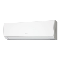
Do you have a question about the General AOHS12LDC and is the answer not in the manual?
Details electrical parameters like power source, frequency, current, input watts, E.E.R., COP, moisture removal, and air circulation.
Provides information on the compressor type, discrimination, and refrigerant used.
Specifies fan motor power source and speed ratings for indoor and outdoor units.
Lists the gross and net weight for both the indoor and outdoor units.
Details sound pressure levels for indoor and outdoor units at various operating modes.
Outlines refrigerant pipe length, full charge amount, and additional refrigerant requirements.
Provides the physical dimensions (Height x Width x Depth) of the indoor unit.
Provides the physical dimensions (Height x Width x Depth) of the outdoor unit.
Illustrates the refrigerant flow path during cooling operations.
Illustrates the refrigerant flow path during heating operations.
Specifies the diameter of the liquid and gas refrigerant pipes.
Presents the electrical circuit diagram for the indoor unit components.
Presents the electrical circuit diagram for the outdoor unit components.
Details the connection points for the air clean unit to the PCB.
Shows the wiring and connection points for the fan motor.
Outlines the circuit connections for the switch PCB assembly.
Details the connections and pinouts for the main controller PCB.
Shows the wiring and connections for the indicator PCB.
Details the power supply circuit within the controller PCB.
Details the circuitry related to the reset function.
Details the circuitry for handling thermistor inputs.
Details the circuit for detecting various voltage levels.
Details the circuitry for the panel switches.
Details the circuit controlling the fan motor input.
Details the circuitry for operating the louver mechanism.
Details the circuitry controlling the power relay.
Details the circuitry for serial communication interfaces.
Details the circuitry for the air purifier operation.
Details the GP1UM261R integrated circuit and its connections.
Details the pin assignments and connections for the CN201 connector.
Shows the connections to the inverter assembly.
Shows the connections to the outdoor unit controller PCB assembly.
Details the wiring for the discharge temperature thermistor.
Details the wiring for the pipe temperature thermistor.
Details the wiring for the outdoor temperature thermistor.
Lists codes and descriptions for serial communication errors.
Lists codes and descriptions for indoor unit thermistor faults.
Lists codes and descriptions for outdoor unit thermistor faults.
Lists codes and descriptions for indoor unit control errors.
Lists codes and descriptions for outdoor unit control errors.
Lists codes and descriptions for indoor fan motor errors.
Lists codes and descriptions for refrigerant cycle abnormalities.
Lists codes and descriptions for errors in optional functions.
Lists error codes related to model identification.
| Brand | General |
|---|---|
| Model | AOHS12LDC |
| Category | Air Conditioner |
| Language | English |


 Loading...