Все каталоги и инструкции здесь: http://splitoff.ru/tehn-doc.html
En-3
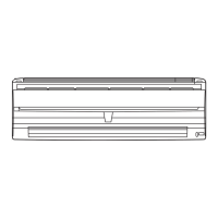
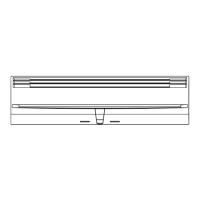
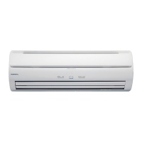
Fig. 1 Indoor Unit
1 Operating Control Panel (Fig. 2)
2 MANUAL AUTO button
3 Remote Control Signal Receiver
4 Indicator Lamps (Fig. 3)
5 OPERATION Indicator Lamp (red)
6 TIMER Indicator Lamp (green)
● If the TIMER indicator lamp flashes when
the timer is operating, it indicates that a
fault has occurred with the timer setting
(See Page 13 Auto Restart).
7 SWING Indicator Lamp (orange)
8 Intake Grille (Fig. 4)
9 Air Filter
0 Air Flow Direction Louver
A Right-Left Louver
(behind Air Flow Direction Louver)
B Drain Hose
C Power Supply Plug
D Power Supply Cord
E Air Cleaning Filter (optional)
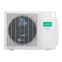
Fig. 5 Outdoor Unit
F Intake Port
G Outlet Port
H Pipe Unit
I Drain port (bottom)
Fig. 6 Remote Control Unit
J SLEEP button
K MASTER CONTROL button
L SET TEMP. button ( / )
M Signal Transmitter
N OFF TIMER button
O ON TIMER button
P SET TIMER button
Q CANCEL TIMER button
R FAN CONTROL button
S START/STOP button
T AIR FLOW DIRECTION button
U SWING LOUVER button
V ACL button
W TEST RUN button
● This button is used when installing the
conditioner, and should not be used un-
der normal conditions, as it will cause the
air conditioner’s thermostat function to op-
erate incorrectly.
● If this button is pressed during normal op-
eration, the unit will switch to test opera-
tion mode, and the Indoor Unit’s OPERA-
TION Indicator Lamp and TIMER Indicator
Lamp will begin to flash simultaneously.
● To stop the test operation mode, press the
START/STOP button to stop the air condi-
tioner.
X Remote Control Unit Display (Fig. 7)
Y Transmit Indicator
Z Operating Mode Display
[ Timer Mode Display
OFF TIMER Mark:
ON TIMER Mark:
SLEEP TIMER Mark:
\ Fan Speed Display
] Temperature and time display
It displays the temperature setting. How-
ever, when making the Timer setting, it will
display the Timer time. (The temperature
setting will reappear after finishing the
timer setting)
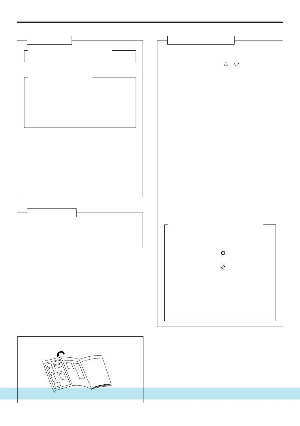
NAME OF PARTS
● Refer to the folded out page on the cover.
9312175024-01_en.pm6.5 2004.2.5, 8:58 AM3
 Loading...