Description Function
1 COM1 Port
Serial Interface to connect an UPS or another device with a original RS232 cable
2 COM2 Port
To connect additional devices for example (GSM Modem, temperature and humidity sensor,
SENSORMANAGER_II, Fieldbus devices (MODBUS RS232, Profibus, LONBus, etc.).
Available at CS141L, CS141SC, CS141MINI & CS141R_2 = RS232
Available at CS141LM & CS141SCM =RS485
(not equipped CS141BL, CS141BSC)
3 LAN Port RJ 45
Ethernet 10/100 Mbit Interface with integrated status LEDs
(green LED: Connection to network established, yellow LED: network traffic)
4 DC Input
external device: supplied by a 12V switching adapter (delivered with the device)
internal device: supplied via the slot interface of the device
5 AUX
Equipped at CS141L, CS141LM, CS141SC and CS141SCM to connect CON_R_AUX4
and BACS etc.
6 Status LEDs
(red / green)
Operation Status CS141 LED Notification
Unpacking the operating system (update procedure) red blinking
Error while unpacking the operating system red fast blinking
Boot process of the operating system red long on
Communication to external device lost (e. g. UPS) red and green
Normal operation - connection to external device established green blinking
7 Slide Switch
DIP Switch
For switching between different boot options
.
Slide Switch in the middle position / 1 + 2 position OFF: To set the
CS141 in the configuration mode and activated the default IP address
10.10.10.10. after a cold start.
Slide Switch in the right position / 1 position OFF + 2 position ON:
DHCP Mode, the IP is set by the DHCP Server. Check the MAC address
of your device to identify your device in the network.
Slide Switch in the left position / 1 position ON + 2 position OFF:
The network settings of the HTTP interface are used it is also possible
to configure DHCP Mode.
8 USB
5
3
2
6
7
1
8
4
CS141SC
CS141L
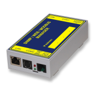
CS141MINI
5
3
2
6
7
2
3
6
7
Slot
Version
External
Version
CS141 SNMP / WEB / MODBUS MANAGER
Version: 2017-11-23