English
6" Bench Grinder with Lights
Operator’s Manual GBG600L
ASSEMBLY AND ADJUSTMENTS
WARNING: Always be sure that the tool is switched off and unplugged
from the power source before adjusting, adding accessories, or checking a
function on the tool
.
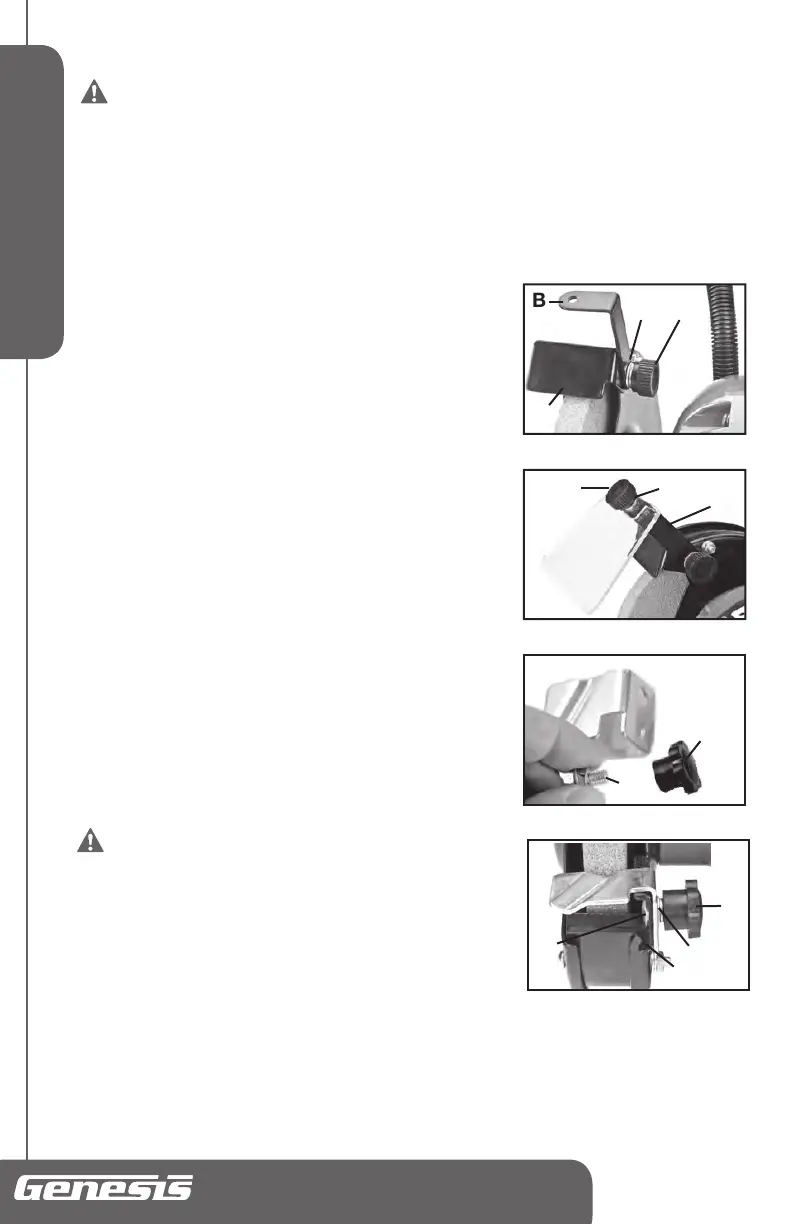
Attaching and Adjusting Spark Guards and Eye Shields (FIG 3,4)
NOTE:
Alwayschecktoensuretheeyeshieldsarecorrectlyattachedandthesparkguardsare
correctlyadjustedeachtimethegrinderisused.Eyeshieldsandsparkguardsmustbeattachedover
eachgrindingwheel.
Thereisaleftandarightsparkguard.ConsultFIG3to
properlydeterminethemountingpositionofeachsparkguard.
FollowthestepstoattachtheSparkGuardandEyeShieldon
theLEFTsideofthegrinder.
1.InsertBracketLockingKnob(H)throughabiglockwasher
(M),abigatwasher(K),theeyeshieldbracket(B)andthe
LEFTsparkguard(C),thenscrewintotheholeintheleft
wheelguard.Tightensufcientlytoholdthesparkguard
andtheeyeshieldbracketinplace.(SeeFIG3)
2.Adjustthesparkguardtomakeitsloweredgeabout1/8"
(3.2mm)awayfromthegrindingwheelface.Rotatethe
wheelbyhandonerevolutiontoensurethewheelcanrotate
withoutcontactingwiththesparkguard.Firmlytightenthe
lockingknob(H)tosecurethesparkguardandeyeshield
bracketontothewheelguard.
3.Inserttheshieldlockingknob(G)throughastarwasher(N)
andasmallatwasher(J)andtheeyeshield(P),andthen
screwandtightensecurelyontotheeyeshieldbracket(B)
(seeFIG4)
RepeattheabovestepstoattachtheRIGHTsparkguardand
theeyeshieldontherightsideofthegrinder.
Attaching and Adjusting Tool Rests (FIG 5,6)
Thetoolrestsarerequiredforeachhighspeedgrindingwheel
toassistinthegrindingoperation.
WARNING: Never use a bench grinder on
which tool rest has not been attached or where
the tool rest has not been correctly adjusted.
NOTE:
Thereisaleftandarighttoolrest.Thetoolrestwith
v-groove(E)istheleftsidetoolrest(SeeFIG5).Whenproperly
mountedwiththeslottedportionofthetoolrestboltedushto
thetoolrestbracket,thetoolrestwillbepositioneddirectlyin
frontofthegrindingwheel.
1.HoldtheLEFTtoolrest(E)inthecorrectpositionagainstthetoolrestbracket(2)onleftwheel
guard(seeFIG6).
2.Inserttoolrestbolt(O)throughtoolrestbracket(2)andtoolrest(E),followedbyasmallatwasher
(J),asmalllockwasher(L),andthetoolrestlockingknob(I).
3.Tightenthelockingknob(I)sufcientlytosupportthetoolrestbutstillallowingthetoolresttoslide
inwardsandoutwards.
B
FIG3
H
C
M
K
FIG 5
E
I
O
FIG 4
G JN
P
B
FIG 6
L
E
J
I
2
O
 Loading...