November 2016 Service and Repair Manual
Manifolds
Part No. 1272220GT GS-2669 DC • GS-3369 DC • GS-4069 DC 65
How t o Adj ust t he Pl atf orm U p R eli ef V alv e - M od els wi tho ut P latf orm Ov erl oad
How to Adjust the Platform Up
Relief Valve - Models without
Platform Overload
Note: Verify the hydraulic oil level is within the top 2
inches / 5 cm of the sight gauge.
1 Connect a 0 to 5000 psi / 0 to 350 bar
pressure gauge to test port #1 (TP1) on the
function manifold.
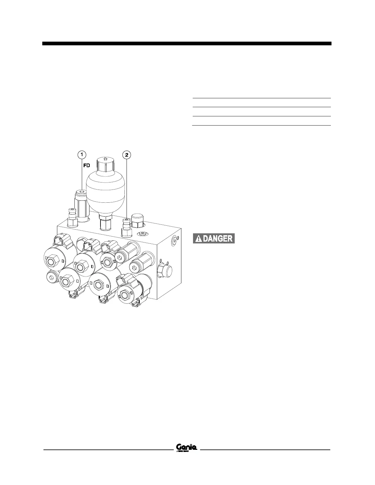
1 platform up relief valve
2 test port #1
2 Using a suitable lifting device, place and
secure the maximum rated load in the center
of the platform deck.
-2669
-3369
-4069
3 Press and hold the lift function enable button
and platform up button. Allow the platform to
raise completely, then continue activating the
lift function while observing the pressure
reading on the pressure gauge. Note the
pressure. Refer to Specifications,
Hydraulic
Component Specifications
.
4 Hold the lift relief valve with a wrench and
remove the cap.
5 Adjust the internal hex socket. Turn it
clockwise to increase the pressure or
counterclockwise to decrease the pressure.
Install the relief valve cap.
-
over hazard. Failure to adjust
the relief valves to specification
could result in
the machine
tipping over, causing death or
serious injury. Do not adjust the
relief valve pressures higher
than specifications.
6 Repeat this procedure beginning with step 3 to
confirm the relief valve pressure.
7 Lower the platform to the stowed position.
8 Using a suitable lifting device, remove the
weight from the platform.
 Loading...