5
ENGLISH
AUTOMATED SYSTEM FALCON
Fig. 1
10
20
30
40
50
60
70
80
90
100
0
12345678910
10 11 12
Percentuale
i lav. %
Tiem
o
h
% Duty cycle
% Fréquence
d'utilisation
% Benutzungs-
frequenz
% Frecuencia
de utilización
Zeit
Std.
Tem
s
h
Time
h
Tem
o
h
Fig. 3
Fig. 2
168
225
Use frequency graph
Dimensions in mm
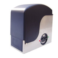
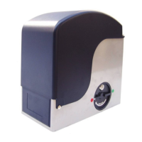
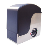
1) Foundation plate
2) Gearmotor
3) Equipment housing
("C" versions)
4) Control board
("C" versions)
5) Mechanical stop limit
6) Pinion
7) Key-operated release
8) Slots and securing nuts
9) Side guards
10) Motor cover
These instructions apply to the following models:
FALCON 14 - FALCON 14C - FALCON 20- FALCON 20C - FALCON 15 -
FALCON 15 C - FALCON 20 3PH
The FALCON automated system for sliding gates is an electro-mechanical
operator transmitting motion to the sliding leaf via a rack and pinion or
chain appropriately coupled to the gate.
The non-reversing system ensures the gate is mechanically locked when the
motor is not operating and, therefore, no lock needs to be installed.
The gearmotor does not have a mechanical clutch and, therefore,
requires a control equipment with adjustable electronic clutch ensuring the
necessary anti-crushing safety.
A handy manual release with customised key makes it possible to move
the gate in the event of a power cut or fault.
In the "C" version of the gearmotor, the electronic control equipment is
housed inside the operator.
The FALCON automated system was designed and manufactured to
control access of vehicles. Avoid any other use whatever.
1. DESCRIPTION AND TECHNICAL SPECIFICATIONS
2. DIMENSIONS
3. MAXIMUM USE CURVE
The curve makes it possible to
establish maximum work time
(T) according to use frequency
(F).
With reference to IEC 34-1
standard, the FALCON
gearmotor operating at S3
service, can function at a use
frequency of 40%.
To ensure efficient operation,
operate in the work range
below the curve.
Important: The curve is
obtained at a temperature of
20°C. Exposure to the direct
sun rays can reduce use
frequency down to 20%.
Calculation of use frequency
The percentage of effective
work time (opening + closing)
compared to total time of cycle
(opening + closing + pause
times).
Calculation formula:
Ta + Tc
% F = X 100
Ta + Tc + Tp + Ti
where:
Ta = opening time
Tc = closing time
Tp = pause time
Ti = time of interval between two complete cycles
4. ELECTRIC EQUIPMENT (standard system)
1) Operator with equipment
2) Photocells
3) Key-operated push-button
4) Flashing lamp
5) Radio receiver
NOCLAFLEDOM
41
C41
02
C02
51
C51
hP302
ylppusrewoP)%01-%6+( zH05~V032~V511
~V004
zH05
)W(rewopdebrosbA 056008017048
)A(t
nerrucdebrosbA 8.25.37.62.2
)mpr(rotomcirtcelE 004100710041
)Fµ(roticapactsurhT 610206-
)Nad(noinipnotsurhT 01105103158
1
)mN(euqroT 53548306
)C°(noitcetorplamrehtgnidniW 041-
)gK(thgiewxamfaeL 0041000200510002
noinipfoepyT 4eludom61Z
)n
im/m(deepsetaG 011101
)m(htgnel.xametaG 02
hctiwstimilfoepyT lacinahcem
hctulC )tnempiuqeees(cinortcele
ycneuqe
rfesU)hpargees( %04-3S
-3S
%05
)C°(erutarepmettneibmagnitarepO 55+÷02-
)gK(thgiewrotomraeG 4151
ssalcnoitcetorP
44PI
snoisnemidllarevorotomraeG
)mm(HxDxL
2.gifees