ENGLISH
CONTROL UNIT FOR BARRIERS
OPERATING INSTRUCTIONS INSTALLATION INSTRUCTIONS
1. DESCRIPTION
The LYNX 06control units are designed and built for managing electro mechanical barriers for controlling residential
accesses.
The two models differ in their voltage:
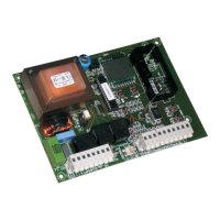
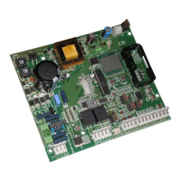
Lynx 06: Power supply 230V
Lynx 06: Power supply 115V
Thanks to their wide ranging number of selectable parameters, these control units can be adapted to your requirements
guaranteeing optimal operation of the automated system.
The possibility of managing an encoder for detecting any obstacles enables you to further increase the safety level
of the automated system.
Programming the main operating parameters is done by pressing two keys on the control unit and is shown on the
generous back lit display. During normal operation, the display shows the status of the automated system at all times.
Learning the work cycle and the mechanical stop-points is performed automatically while the first cycle is being
performed (whenever power is cut, the control unit searches the stop-points both at opening and closing).
The six integrated LEDs constantly indicate the inputs status.
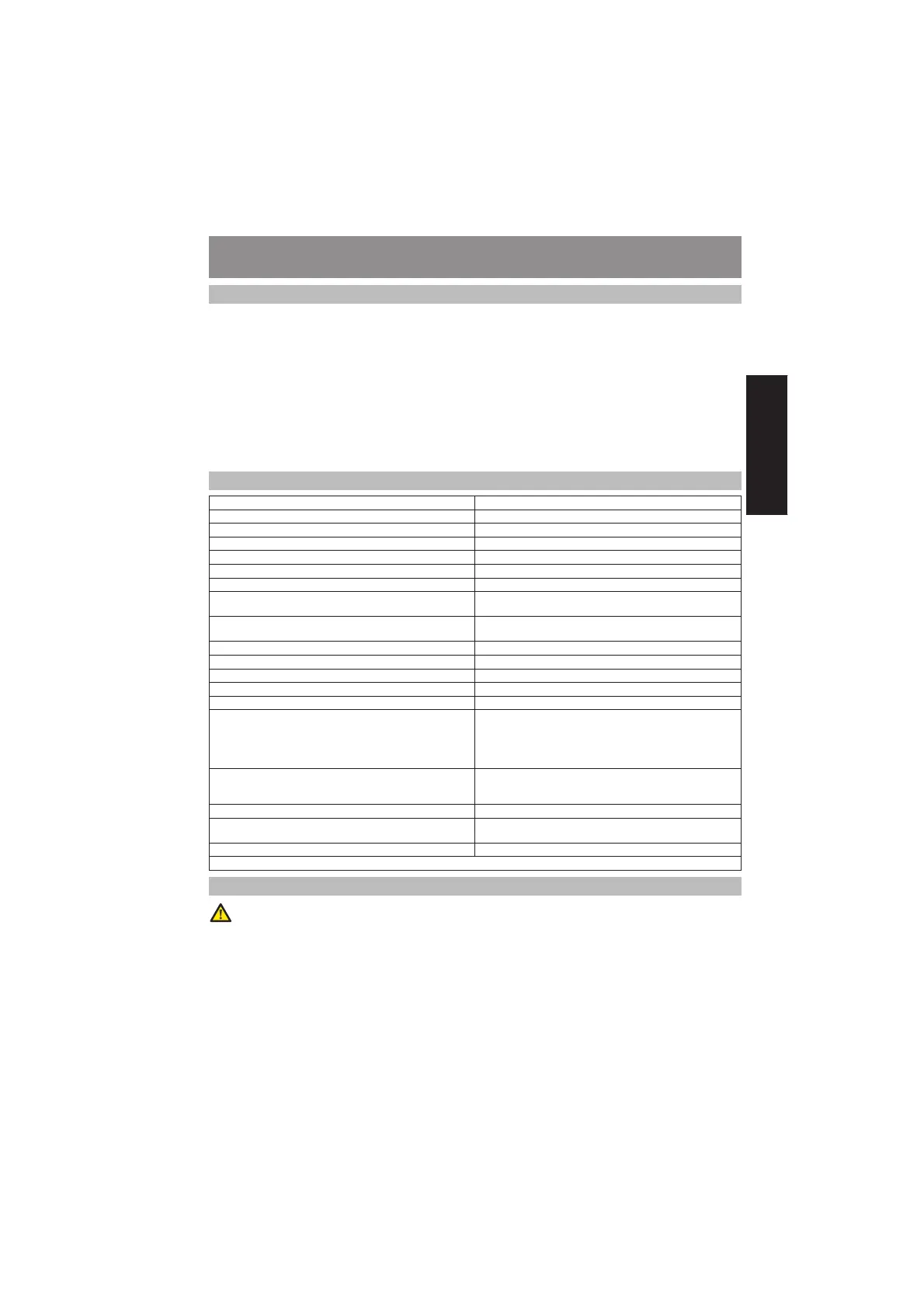
2. TECHNICAL SPECIFICATIONS
Supply voltage of control unit
230/115 Vac 50/60 Hz
a
Absorbed power 3 W
Motor absorbed power 500 W
Accessories max. load 500 mA
Power supply and indicator light max. load 230 Vac 25 W
Power supply and max load of barrier status indicator light 24 Vdc 5 W
Operating ambient temperature -20°C +55°C
Protective fuses
F1= T5A (Transformer and motor primary winding)
F2= T500mA (accessories and indicator light)
Function logics
Automatic / Step-by-step automatic /Semiautomatic
/Step-by-step semiautomatic / Condo
Opening / closing time In self learning mode during first manoeuvre
Pause time Nine levels selectable up to a maximum of 4 minutes
Motor power Adjustable on several levels
Slow-down time Three selectable levels
Obstacle detection With optional encoder
Selectable functions
Operates with or without encoder / Encoder sensitivity/
Automatic closure / Open input operation/Condo
function / Slow-down percentage/ Heating function /
Immediate closure / Timer function / Soft start / Photocells
operation /Maintenance request
Terminal board inputs
Opening / Closure / Photocells / Opening travel limit
device /Closure travel limit device / Stop / Mains power
supply / Earthing
Inputs with connector Radio module / thrust capacitor / encoder
Terminal board outputs
Power supply to accessories / Flashing lamp / Motor /
Indicator light
Board dimensions 147 x 112 mm
a
According to board model, 230 Vac or 115 Vac.
3. PREPARATORY ACTIONS
To ensure peoples safety, all warnings and instructions in this booklet must be carefully observed. Incorrect
installation or incorrect use of the product could cause serious harm to people.
Keep the instructions for future reference.
Make sure that an adequate differential switch is installed upstream of the system as specified by current safety
regulations.
On the main power supply, install a thermal breaker with omnipolar switching.
Make sure that an adequate earthing system is available.
To lay cables, use adequate rigid and/or flexible tubes.
Always separate the 230/115 Vac power cables from low voltage connections, using separate sheaths to avoid
possible interference.
•
•
•
•
•
•
•
 Loading...