Do you have a question about the Genius LYNX 06 and is the answer not in the manual?
Essential safety instructions for installers covering product usage, environment, and electrical safety.
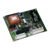
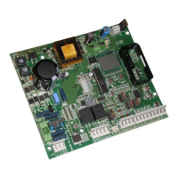
Connection details for earthing, power supply, flashing lamp, and motor.
Details on connecting the optional encoder and its function in safety operations.
Connection instructions for opening, common, and closing travel limit devices.
Connecting various inputs (Close, Open/Close, Safety, Stop) and outputs (indicator, accessories).
Instructions for connecting the thrust capacitor to the CN5 connector.
Step-by-step guide to storing 868 MHz radio controls for both channels.
Procedure for storing 433 MHz radio controls, including remote storage.
Instructions for irreversibly deleting all stored radio control codes.
Explanation of the function of the 8 control LEDs indicating input status.
Steps to access and modify operational parameters at first start-up.
Settings for motor power, encoder sensitivity, and obstacle detection.
Configuration for reclosure, input behavior, condo, slowdown, heating, and immediate closure.
Settings for soft start, safety devices, assistance request cycles, and function details.
Detailed explanation of the assistance request function and cycle resetting.
Logic for Automatic operation with safety devices active for closing and opening.
Logic for Automatic Step-by-Step operation with specific safety device behavior.
Logic for Semi-automatic operation with specific safety device behavior.
Logic for Stepped Semi-Automatic operation with safety devices active for closing and opening.
Logic for Condo operation with safety devices active for closing and opening.
| Brand | Genius |
|---|---|
| Model | LYNX 06 |
| Category | Control Unit |
| Language | English |