ENGLISH
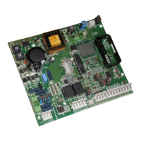
4. BOARD LAYOUT
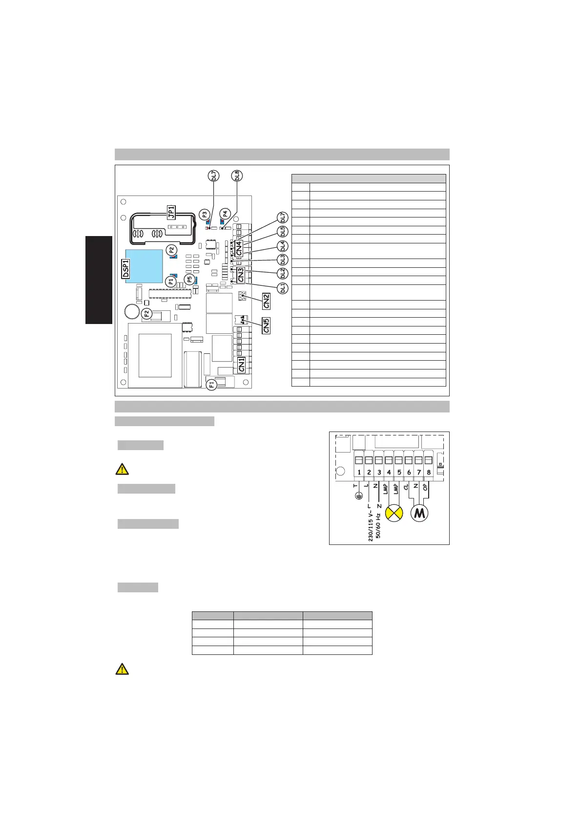
Components
CN1 Power supply terminal-board
CN2 Encoder connector
CN3 Travel limit terminal-board
CN4
Terminal board for commands / powering accessories
CN5 Capacitor connector
JP1 Connector for radio module
DSP1 Display
F1
Fuse for transformer primary winding/Motor
power supply
F2 Fuse for accessories/indicator light
P1 Parameters adjustment push-button
P2 Parameters adjustment push-button
P3
OPEN/CLOSE radio channel memory storage
push-button
P4
CLOSE radio channel memory storage push-button
P5 RESET push-button
DL1 FCA input LED
DL2 FCC input LED
DL3 CLOSE input LED
DL4 OPEN/CLOSE input LED
DL5 FSW input LED
DL6 STOP input LED
DL7 OPEN/CLOSE radio channel LED
DL8 CLOSE radio channel LED
5. CONNECTION AND OPERATION
5.1. CN1 TERMINAL-BOARD
5.1.1. EARTHING
Terminal 1. Connect the yellow-green power cable to this terminal.
The connection is absolutely necessary for correct operation of the
control unit.
5.1.2. POWER SUPPLY
Terminals 2 & 3. Connect, to these terminals, the two cables incoming from
the 230/115 Vac power supply line according to board model.
Connect the neutral wire to terminal 3 and the phase to terminal 2.
5.1.3. FLASHING LAMP
Terminals 4 & 5. Output 230/115 Vac max. 25 W. The flashing lamp power
cable must be connected to these terminals. The flashing lamp is active
while the automated system is moving, whereas when the system is open
or closed, it stays OFF. Before the opening manoeuvre, the flashing lamp pre-flashes on steady beam for 0.5 sec. If the
assistance request function has been activated, an when the set number of cycles has been reached, at the end of
the closing manoeuvre, the flashing lamp continues to flash for another 5 seconds, indicating that the set cycles have
been reached. For the cycles resetting operation, see paragraph 10.1.
5.1.4. MOTOR
Terminals 6, 7 & 8. Output 230/115 Vac max. 500 W. Connect the motor power cables to these terminals. For the cable
connection sequence, refer to the following table:
Terminal No. Motor 230 Vac Motor 115 Vac
6 Black Black
7 Blue / Grey White
8 Brown Red
1 Yellow Green Green
The colour of the wires connected to terminals 6 & 8 can be reversed according to motor rotation direction
 Loading...