ENGLISH
13
4.2. Preliminary checks
To ensure a correct operation of the automated system, make sure the following requirements are observed as for the gate structure
(existing or to be created):
• the mechanical parts must conform to the provisions of Standards EN 12604 and EN 12605.
• leaf length in compliance with the operator specifications.
• sturdy and stiff structure of the leaves, suitable for automation
• regular and uniform movement of the leaves, without any friction and dragging during their entire opening
• stiff hinges in good conditions
• presence of both opening and closing mechanical limit stops
• presence of an efficient earthing for electrical connection of the operator
Perform any necessary metalwork job before installing the automated system.
The condition of the gate structure directly affects the reliability and safety of the automated system.
4.3. Installation dimensions
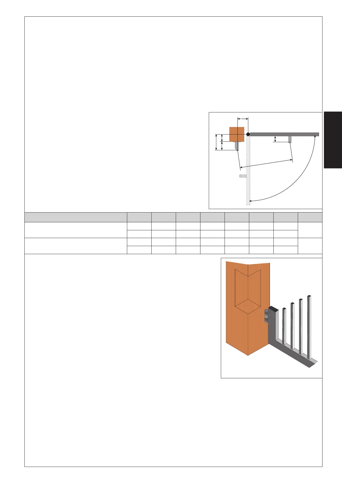
Determine the fitting position of the operator with reference to Fig.4.
Check with care if the distance between the open leaf and any obstacles
(walls, fences etc.) is higher than the operator dimensions
(1)
operator useful travel
(2)
max. dimension
(3)
min. dimension
4.3.1. General rules to determine the installation dimensions
• to obtain 90° leaf openings : A+B=C
• to obtain leaf openings exceeding 90° : A+B<C
• Smaller A and B dimensions determine higher peripheral speed of the leaf.
• Limit the difference between A and B dimension within 4 cm: higher differences
cause great speed variations during the gate opening and closing movement.
• Keep a Z dimension in such a way that the operator does not strike the pillar.
• in the LS versions the limit switches are triggered for the first and the last 30 mm.
Therefore use such A and B dimensions in order to use the whole operator travel.
Shorter travels could limit or cancel the limit switch adjustment range.
If the pillar dimensions or the hinge position do not allow the installation of the operator,
a niche on the pillar, as shown in Fig. 5, should be created in order to maintain the A
dimension as determined. The niche should be dimensioned in such a way to enable
easy installation, operator rotation and operation of the release device.
ledoM
α
A B C
)1(
D
)2(
Z
)3(
L E
)3(
-V511-003/423/003LARTSIM
°0954154109258060111
54
°01102153159206060111
-V511-004/424/004LARTSIM
°09591591093521070921
54
°01107
1071093011060921
Fig. 4
Fig. 5





 To Next Page