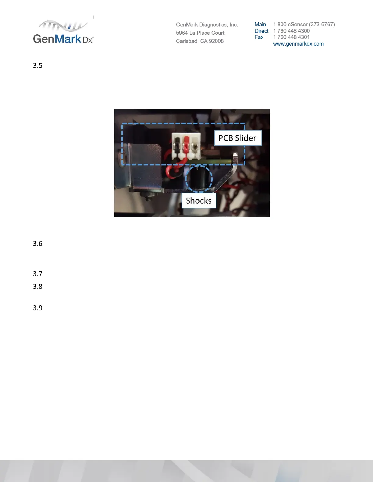
Examine each of the six PCB sliders (located at the back of the Tower), which are mounted on two
plastic shocks as shown in Figure 4 . If either shock is cracked or damaged, the PCB slider will not be
seated securely and can impair proper connection to the bay. Examine shocks from both sides of the
Tower. Report damaged shocks as Tower OOBF to Technical Support; request an RMA and
replacement Tower from Customer Service.
Figure 4 PCB Slider and Shocks
To inspect the sliders, reach into the Tower slot and strongly wiggle the slider up and down and side
to side. There should be a fair amount of tension on the shock mounts. If the mounts can move easily
in any direction, the Tower will need replacement.
Verify that the washable filter is on the rear panel of each Tower.
If configuration is an NP, please continue to refer to the 3 Bay (NP) installation instructions to set
PCBA slider positions.
Locate the ePlex bay slots in the tower, these will be referred to as numbers 1 – 6 from top to bottom
(see Figure 5 for reference).
Note: ePlex bay slot positions 1, 3, and 5 will be populated with bays.
• Bay position 3 will become electronic system position 2
• Bay position 5 will become electronic system position 3
• Bay position 1 DOES NOT CHANGE (remains electronic system position 1)
• ePlex bay slots 2, 4, and 6 will be left empty.
 Loading...