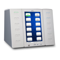
Figure 8 ePlex Tower Configurations
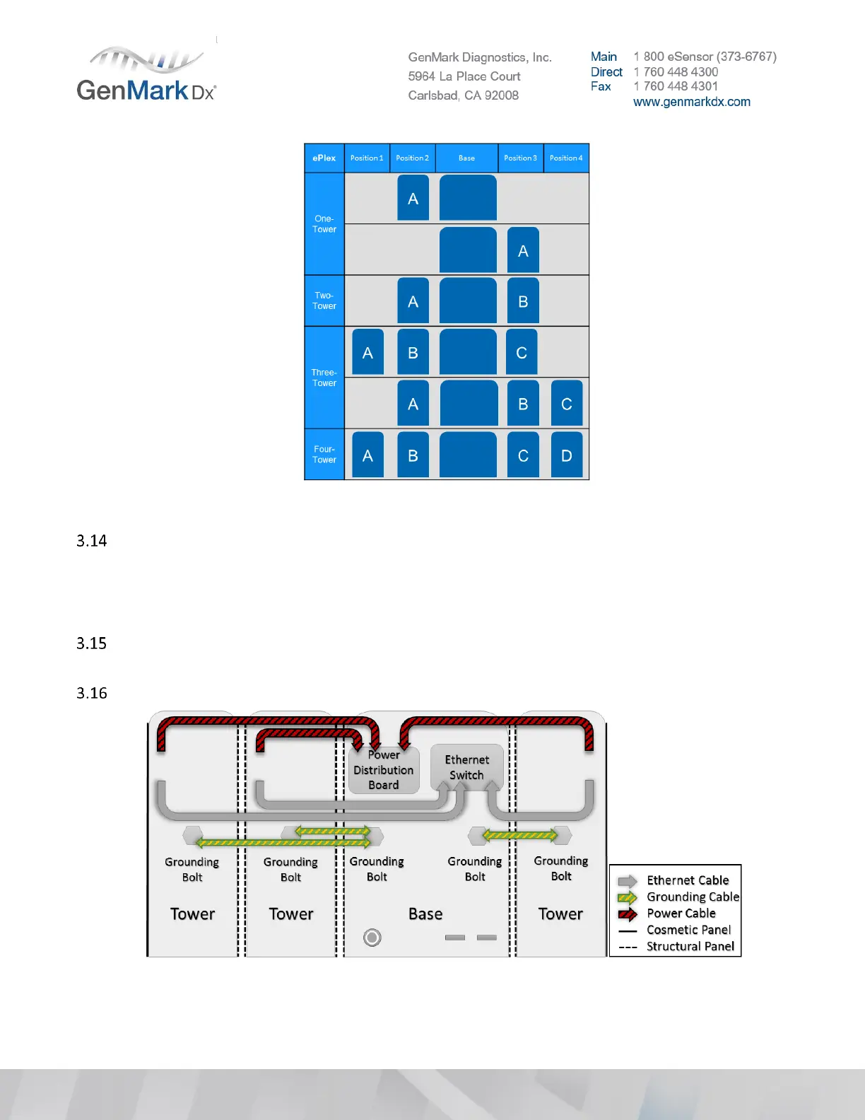
Cut the zip ties around the cables, route and connect the following.
• Power cable(s) to Base Power Distribution Board
• Grounding cable(s) from Tower grounding bolt(s) to Base grounding bolt(s).
• Ethernet cable(s) to Base Ethernet Switch
If installing a four (4) Tower system, or a two (2) Tower system with both towers on the right-hand
side, Tower position D’s power cable needs to have added strain relief.
See the following images for an understanding of the cable routing and connection process.
Figure 9 Tower cable routing positions
 Loading...