CAUTION: RED/YELLOW and BROWN/YELLOW wire to be capped when not in use.
This wire is for tandem connection only. DO NOT connect to any other circuit.
WIRING TWO OR MORE ALARMS
Tandem Installation
NOTICE: ALL SMOKE ALARMS IN A TANDEM INSTALLATION MUST BE
CONTROLLED BY THE SAME FUSE OR CIRCUIT BREAKER. OTHERWISE
TANDEM UNITS WILL NOT OPERATE. TANDEM WILL OPERATE IN THE EVENT
OF AC POWER FAILURE IF BATTERY IS CONNECTED TO THE SMOKE ALARM.
LIMITATIONS: A maximum of 12 smoke alarms (S1209) may be connected
together. Do not exceed 125 feet between each device. Do not exceed 1125 feet
between first and last smoke alarm.
NOTICE: A MAXIMUM OF 12 SMOKE ALARMS OF S1209 WITH THE RELAY
OPTION (F) MAY BE TANDEM INTERCONNECTED.
Wire used for interconnection shall be in accordance with article 760 of the latest
edition of National Electrical Code (NFPA 70) and must not exceed a resistance of 10
ohms.
w All units connected in tandem MUST get their power from the same circuit, that is,
all smoke alarms in tandem must be controlled by the same fuse or circuit breaker.
w After installation, to verify proper working conditions, all horns must sound in this
system.
w When tandem interconnecting S1209 Series to additional S1209 Series, GN-503
Series or CO1209 Series and the smoke alarm horn sounds but are not
synchronized and the CO horn does not sound the red/yellow wire has been used.
Use brown/yellow wire.
w Use red/yellow wire to tandem interconnect S1209 alarms to Gentex legacy
products. The S1209 Series can be tandem interconnected with the following
Gentex legacy products: 9123 Series, 7139CS Series and GN-300 Series.
w Use brown/yellow wire to tandem interconnect S1209 Series alarms to additional
S1209 Series, GN-503 Series and CO1209 Series.
w If the red/yellow wire is used to interconnect the S1209 Series to additional S1209
Series, GN-503 Series and CO1209 Series, the units will not be tandem
interconnected. The brown/yellow MUST be used.
w Do not tandem using both the red/yellow wire and brown/yellow wire. Only 1
tandem interconnect wire is needed between units.
CAUTION: Failure to observe any of the conditions set forth may cause system
malfunction and damage to the device.
BATTERY INSTALLATION
1. Locate side mounted battery drawer.
2. Open battery drawer by firmly pulling on side lip, then sliding battery drawer open.
3. Insert battery into drawer, terminal side first. Take care to make sure the
appropriate terminal is aligned correctly, (+) terminal on battery to (+) terminal on
alarm metal contact and (-) terminal on battery to (-) terminal on the alarm metal
contact.
4. Rotate battery into drawer and close drawer. Note: the battery drawer will not close
if the battery is installed incorrectly.
5. Slide battery drawer shut until it is snapped into place.
6. Use only Duracell® MN 1604 battery with the S1209 Series smoke alarm.
Available at many retail stores.
7. Push test button to verify battery operation.
NOTICE: UNITS WITH BATTERY BACK-UP WILL NOT PROVIDE POWER OR
TRANSMIT AN ALARM TO OTHER AC ONLY UNITS IN THE EVENT OF AN AC
POWER FAILURE. ALL BATTERY BACK-UP UNITS IN TANDEM WITH GOOD
BATTERIES WILL OPERATE NORMALLY DURING AN AC POWER FAILURE A
MINIMUM OF 24 HOURS.
550-0008
Pg. S-5
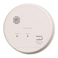
S1209 / S1209F TANDEM INTERCONNECT WIRING DIAGRAM
LIMITATIONS: Maximum of 12 smoke
alarms may be connected together.
Do not exceed 125 feet between each
smoke alarm. Do not exceed 1125
feet between the first and last smoke
alarm.
Use BROWN/YELLOW wire to
tandem interconnect S1209 Series
alarms to additional S1209, CO1209
and GN-503 Series. DO NOT USE
RED/YELLOW WIRE TO
INTERCONNECT S1209, CO1209
AND GN-503 SERIES
NOTE: S1209 AND S1209F CAN BE
TANDEM INTERCONNECTED WITH
THE FOLLOWING GENTEX
LEGACY PRODUCTS: 9123, 7139CS,
GN-300 AND GN-303 SERIES.
THESE PRODUCTS WILL NOT
ACTIVATE FOR A CO EVENT WHEN
TANDEM INTERCONNECTED TO A
GENTEX CO OR SMOKE/CO
ALARM.
LIMITATIONS: Maximum of 12 smoke alarms may be connected together. Do not
exceed 125 feet between each smoke alarm. Do not exceed 1125 feet between the
first and last smoke alarm.
1. Run a minimum of 16 gauge, 3-conductor cable, plus ground (4 wires) to the first
junction box from a power supply and between all smoke alarms that are to be
connected together. Use ANSI/UL Listed Class 1 wire. Power limited cable for
multiple tandem connections is available at many commercial electrical retail
stores.
NOTICE: WHEN USING BOTH TANDEM CONNECTIONS, 4-CONDUCTOR CABLE,
PLUS GROUND (5 WIRES) WILL BE USED.
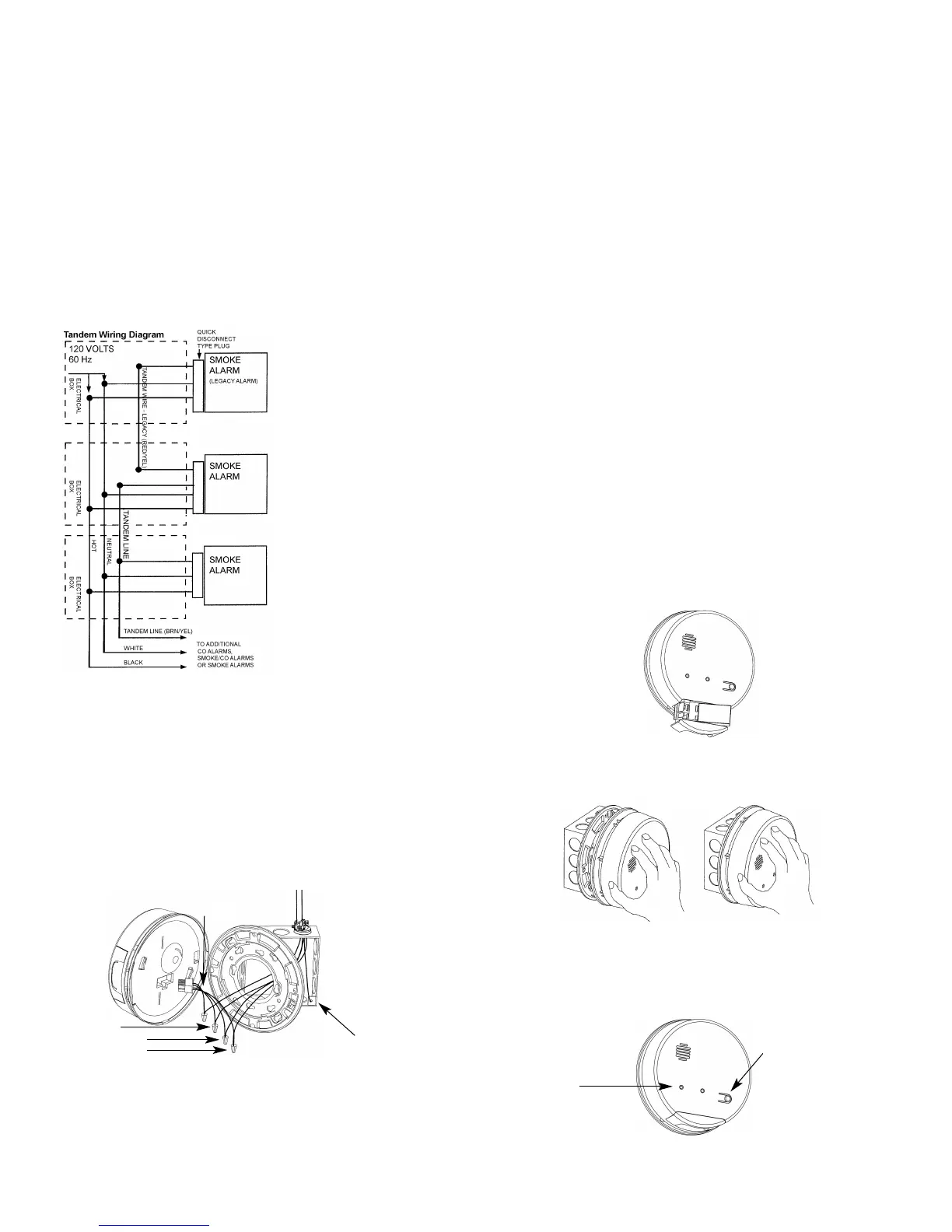
2. Make wire connections to the supplied plug-in connector as follows: black to black,
white to white, 3rd conductor to the red/yellow wire for legacy Gentex products or
the brown/yellow wire for new. The red/yellow wire or brown/yellow wire should be
stripped to make the connection. Connect ground wire between metal outlet
boxes.
FIGURE 10
MOUNTING: PLATE & SMOKE ALARM
1. Lace the connector through the provided mounting plate and secure the plate to the
junction box.
2. Plug the wire connector into the smoke alarm base.
FIGURE 9
RED-YELLOW (LEGACY)
BROWN-YELLOW WIRE
4
th
UNINSULATED WIRE
EARTH GROUND - FOR
METAL BOXES ONLY
4-WIRE CABLE
120VAC
BLACK
WHITE
NOTES ON TANDEM INTERCONNECTING MODELS
w DO NOT connect Gentex Smoke Alarms to other manufacturers' smoke alarms.
w A maximum of 18 compatible smoke, heat, CO and/or combination smoke/CO
alarms may be interconnected. No more than 12 of the 18 can be smoke alarms
per NFPA 72.
w No more than 12 Gentex model S1209 or S1209F may be connected in tandem.
w No more than 6 Gentex LEGACY products with Form A/Form C contacts may be
connected in tandem.
3. Place device up to mounting plate, rotating it clockwise until device firmly snap
locks into place. Keep smoke alarm parallel to the mounting plate so tabs on plate
seat correctly into device.
4. Remove dust-cover after all construction is complete. Dust-cover must be removed
prior to power being supplied to the smoke alarm. If the dust-cover is not removed,
operation of smoke alarm will be inhibited.
FIGURE 11
POWER ON
INDICATOR/
SMOKE
INDICATOR
FIGURE 14
PRESS AND RELEASE
BUTTON FOR SELF
TEST. PUSH BUTTON
AND HOLD UNTIL
DEVICE ALARMS
FOR FUNCTIONAL
TEST
NOTICE: REMOVE DUST-COVER BEFORE OPERATING SMOKE ALARM
 Loading...