Do you have a question about the GENUINE HOOLIGAN 170i and is the answer not in the manual?
Details the technical specifications for the Hooligan 170i scooter.
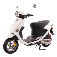
Illustrates the external configuration and component labels of the motorcycle.
Provides torque values for various bolts and nuts used in body and engine assembly.
Outlines essential rules and best practices for performing maintenance procedures safely and correctly.
Lists and illustrates various specialized tools required for maintenance and repair tasks.
Provides systematic procedures for diagnosing and resolving common engine and EMS issues.
Illustrates the interrelationships and positions of various plastic components on the vehicle.
Details the steps for dismantling and removing the main body cover panels.
Details the disassembly of the brake master cylinder and handlebar switch assemblies.
Details the procedure for removing and installing the fuel tank assembly.
Details the procedure for removing the front inner cover assembly.
Covers checking and replacing the engine oil, including volume and procedure.
Explains how to check, clean, and replace the air cleaner element.
Provides step-by-step instructions for installing the motorcycle battery correctly.
Covers the procedure for checking and adjusting the engine's timing mechanism.
Details how to check and adjust the valve clearance for optimal engine performance.
Details how to check the thickness of brake pads for wear and replacement.
Covers checking tire pressure, tread depth, and specifications for wear.
Details how to check and replace fuses using a multimeter.
Explains how to measure engine compression pressure for diagnostic purposes.
Introduces the features and structure of the second-generation Electronic Fuel Injection (EFI) system.
Explains the function, location, and measurement of the crank speed sensor.
Describes the principle, fault phenomena, and measurement of the engine temperature sensor.
Details the TPS principle, measurements, and troubleshooting for idle speed issues.
Details the fuel pump's location, principle, measurement, and troubleshooting for clogging.
Lists and illustrates essential repair and diagnostic tools for the EMS system.
Details how to use the quick diagnostic tool for EMS system troubleshooting and defect code reading.
Covers the steps for disassembling the engine assembly, including back luggage and muffler.
Guides the process of separating the engine from the vehicle's frame.
Covers the steps for disassembling the cylinder head, including fan cover and cooling cowl.
Covers the steps for removing the cylinder, piston pin, and piston rings.
Details the procedure for dismantling the crankcase, including fan, flywheel, and stator removal.
Details the drive pulley, starter clutch, and driven pulley components and their measurement data.
Details the troubleshooting, data, dismantling, and installation of cylinder and piston assemblies.
Provides troubleshooting and data for crankcase and crankshaft components, including measurements.
Covers troubleshooting, disassembly, and checking of the final transmission mechanism.
Covers the steps for removing the front wheel, including brake bolts and axle.
Explains the demolition, check, and installation of the front wheel's sealed ball bearing.
Covers the steps for disassembling the front fork, including handle bar and steering components.
Details the demolition and installation procedures for the rear damper (both right and left).
Details the disassembly, measurement, and installation of front wheel brake pads.
Provides instructions for replacing brake fluid using a pumping unit, with safety warnings.
Illustrates the locations of various Denso electrical components on the vehicle.
Details the process for checking the starter system components: fuse, battery, switch, motor, and relay.
Explains how to check the battery, A.C.G., and charging lines for proper operation.
Provides a method for testing leakage current using an ammeter to identify short circuits.
Covers electrical checks for bulbs, switches, and lighting circuits.
Details measurements for electrical appliances like main switch, horn, and fuel gauge.
Explains relay function, usage, and measurement procedures using a pocket tester.
Details fuse types, ratings, and their specific purposes in protecting circuits.
Details how fuses protect the injection system components and associated failure phenomena.
Presents the wiring diagram for the injection system, including line color coding.
Provides a checklist for diagnosing engine misfire or no injection issues in the system.