Electrical lock
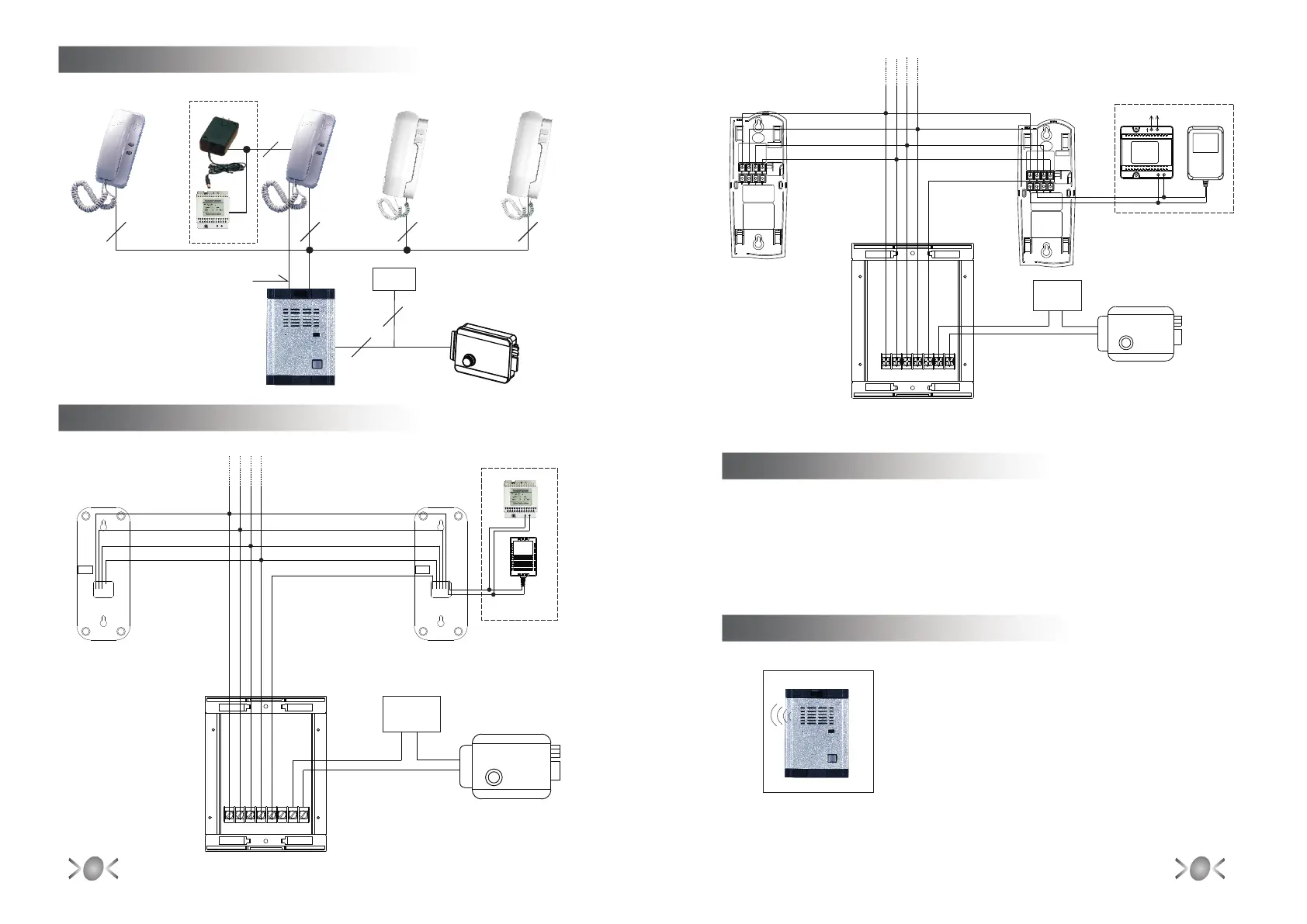
5 System Connection Diagram¡
Green
Yellow
Red
Black
Blue
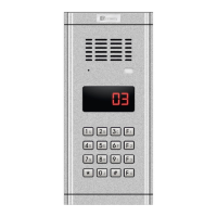
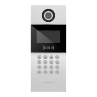
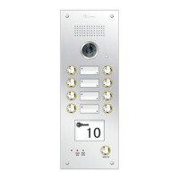
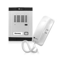
Door station
Accessory
Indoor phone
Adaptor
4¡System Diagram
Door station
2
Power
wire
44 4 4
2
WL-06DFbH1
Electrical lock
Main Indoor phone
Green
Yellow
Red
Black
6 Wire Material¡
1.Wiring between door station and indoor phone: Within the distance of 50 meters, use
wire thicker than RVV5 0.4 multi-copper wire. Wire diameter should be adjusted
according to wire distance.
2.The audio wire between door station and extra handset should be multi copper
wire ( RVV4 0.15 diameter).
¡
¡ ¡
PS-3E
Adaptor
Two options
Adaptor & PS-3E
+ -
Two options
Adaptor & PS-3E
PS-3E
2
Power
101 SOUTSIN GNDPOWERLK- LK+
COM
Power
12V
+ -
Accessory
Indoor phone
Main
Indoor phone
101 SOUTSIN GNDPOWERGND LK
Adaptor
~
AC
AC 220V input
+DC -
~
SOUT
SIN
GND
POWER
101
4(IN)
3(OUT)
2(GND)
1(RING)
7(DC14V)
4(IN)
3(OUT)
2(GND)
1(RING)
5(DC15V)
6(GND)
Electrical lock
Power
12V
+ -
Two options
Adaptor & PS-3E
Door station
WL-06DFbH1 WL-06DFaD WL-06DFbD
3
4
7 System Operations¡
1.1
¡ ¡
The indoor phone will ring when the visitor press the
Call button on the door station
 Loading...