Do you have a question about the Geokon 4500 Series and is the answer not in the manual?
Details the process of saturating filter tips to ensure accurate pressure readings.
Specific instructions for saturating standard low air entry filters.
Procedures for saturating high air entry ceramic filters.
Steps for saturating the non-removable filter tips of the 4500C model.
Methods to obtain an accurate initial zero reading for data reduction.
The primary recommended method for taking an initial zero reading.
A first alternative procedure for establishing the initial zero reading.
A second alternative procedure for establishing the initial zero reading.
A third alternative procedure for establishing the initial zero reading.
Procedures to verify the piezometer's operational performance and accuracy.
Steps for installing piezometers in standpipes and wells.
Methods for installing piezometers in boreholes, including sealing techniques.
Guidance for installing piezometers in fills and embankments.
Method for installing piezometers in soft soils using direct pushing or driving.
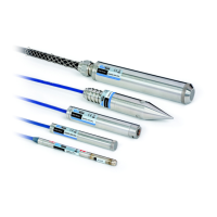
Specific installation and handling instructions for 4500H and 4500HH models.
Procedures for splicing cables and using junction boxes for connections.
Essential measures to protect the piezometer from lightning strikes.
Methods to prevent damage from freezing, particularly to the diaphragm.
Overview and operation of the portable GK-404 readout unit.
Detailed step-by-step guide for operating the GK-404 readout.
Overview of the GK-405 readout system, including components and connectivity.
How to connect sensors with 10-pin connectors to the GK-405.
How to connect sensors with bare leads to the GK-405.
Detailed instructions for operating the GK-405 readout system.
Procedures for measuring temperature using the piezometer's thermistor.
Explains the calculation of pressure from raw readings and calibration factors.
Details how to apply temperature corrections to pressure readings.
Steps for applying barometric corrections to unvented piezometers.
Information specific to the 4500SV vented piezometer model.
Discusses environmental factors that should be observed and recorded.
Technical specifications for standard 4500 series piezometers.
Technical specifications for 4500CR series piezometers.
Specifications for the piezometer's internal thermistor.
Wiring details and pin assignments for standard piezometers.
Provides the equation and data table for 3kΩ thermistors.
Provides the equation and data table for 10kΩ thermistors.
| Type | Vibrating Wire Strain Gauge |
|---|---|
| Model | 4500 Series |
| Resolution | 1 microstrain |
| Operating Temperature | -20°C to +80°C |
| Material | Stainless steel |
| Application | Geotechnical and Structural Monitoring |
| Gauge Length | 6 inches (152 mm) standard, other lengths available |
| Range | 3000 microstrains |
| Accuracy | ±0.1% of full scale |
| Cable | 4-conductor shielded cable |