EasyManua.ls Logo

Geotab GO User Manual

Geotab GO
2 pages
To Next Page IconTo Next Page
Page #1 background imageLoading...
Page #1 background image
1
2006-2018 Mack Vehicles
Installation Guide [for HRN-CK10K2 and HRN-CM24Y1 harnesses]
How to Install
2006-2018 Mack Vehicles
To install the HRN-CK10A2 and HRN-CM24Y1 harnesses in 2006 to 2018 Mack vehicle models, follow the steps below:
Introduction
This installation guide provides information on how to install the HRN-CK10A2 and HRN-CM24Y1 harnesses in 2006 to 2018
Mack vehicle models with fuse box using terminal bus bar. (This document does not apply to Mack cab over models)
Step 1: Locate and remove the fuse box panel.
Step 2 : Connect the red wire from the HRN-CK10A2
harness (labeled BATT) into the second pin
(labeled Battery on the bus bar).
Step 3: Connect the black wire from the HRN-CK10A2
harness (labeled GND) into the eighth pin (labeled
Ground on the bus bar).
Step 4A : Connect the brown wire from the HRN-CK10A2
harness (labeled +J1587) to the fth pin
(labeled serial A on the bus bar).
Step 5A : Connect the green wire from the HRN-CK10A2
harness (labeled -J1587) to the sixth pin
(labeled serial B on the bus bar).
Skip to Step 6A.
BATTERY
GND
SERIAL B SERIAL A
2008-2018 Mack vehicle models, skip to Step 4B.
!
Rev. A1 - 11/2020For the most up-to-date version, please visit : gtb.page.link/6UdU
Question and Answer IconNeed help?

Do you have a question about the Geotab GO and is the answer not in the manual?

Geotab GO Specifications

General IconGeneral
GPSYes
Wi-FiNo
BluetoothYes
CertificationsFCC, IC, CE, PTCRB
Engine DiagnosticsYes

Summary

2006-2018 Mack Vehicles Installation Guide for HRN-CK10K2 and HRN-CM24Y1 Harnesses

Introduction to Harness Installation

Provides an overview of how to install the HRN-CK10K2 and HRN-CM24Y1 harnesses in Mack vehicles.

How to Install 2006-2018 Mack Vehicles

Details the installation steps for HRN-CK10A2 and HRN-CM24Y1 harnesses in Mack vehicles.

Fuse Box Panel and Wiring Connections

Steps for locating the fuse box panel and connecting specific wires to the bus bar.

J1939 Connector and EOL Resistor Installation

Instructions for locating the J1939 connector and installing the EOL resistor.

OBD II Molex Connector Connections

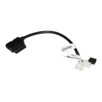
Steps to connect the 12-pin black and 6-pin white OBD II Molex connectors.

Device Installation and Verification

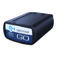
Guide for installing the GO device, securing harnesses, and verifying communication status.

Related product manuals