5.2 Wiring the Beeper and LED to the GV-AS Controller
To wire the beeper and LED to GV-AS210 / 2110 / 400 / 410 / 4110 / 810 / 8110, connect the
control wires of the reader’s Beeper, Red LED or Green LED to any of the outputs on GV-AS
Controller. Note that outputs 9 ~ 16 on GV-AS400 are used for the built-in LED and beeper
settings.
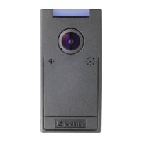
Wiring LED to GV-AS Controller
The diagram below shows the connection for wiring Green LED using GV-RK1352 and GV-
AS810 as an example. For Red LED, use the light red wire instead.
OUT11
OUT12
Wire Color Function
Black GND
Orange Green LED
Light Red Red LED
Wir
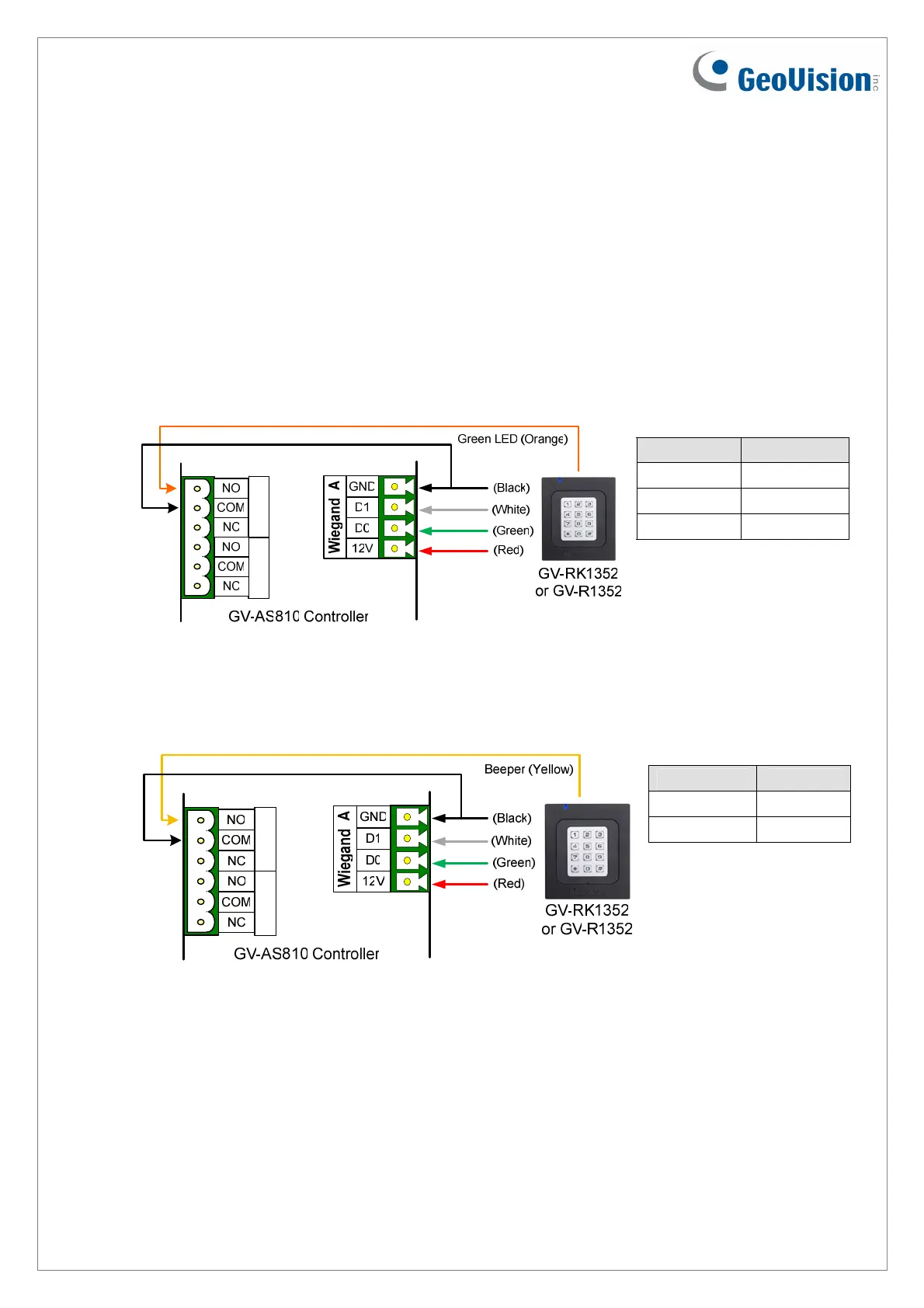
ing Beeper to GV-AS Controller
The diagram below shows the connection for wiring the beeper using GV-RK1352 and GV-
AS810 as an example.
Wire Color Function
Black GND
Yellow Beeper
OUT11
OUT12
December
31, 2014
14

 Loading...