EasyManua.ls Logo

GESTRA NRGT 26-2s User Manual

Default Icon
56 pages
To Next Page IconTo Next Page
Page #1 background imageLoading...
Page #1 background image
Original Installation &
Operating Manual
EN
English
Level Transmitter
NRGT 26-2
NRGT 26-2s
819876-00

Table of Contents

Question and Answer IconNeed help?

Do you have a question about the GESTRA NRGT 26-2s and is the answer not in the manual?

GESTRA NRGT 26-2s Specifications

General IconGeneral
TypeNRGT 26-2s
Operating temperatureMax. 239 °C (462 °F)
Power supply24 V DC
Operating pressureMax. 32 bar (500 psi)
Output signal4...20 mA / HART

Summary

Warning Types

Intended Use

Water Level Control Application

Describes use as a water level controller in steam/hot water systems.

Improper Use Warnings

Basic Safety Precautions

Personnel Qualifications

Functional Safety and SIL

Reliability Data (EN 61508)

Technical Data: Mechanical and Material

Technical Data: Electrical and Performance

Factory Default Settings

Installation Preparation

Installation Procedures

Installing the NRGT 26-2

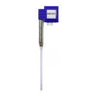
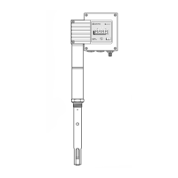
Details the process of installing the NRGT 26-2.

Installing Two Level Electrodes

Provides steps for installing two level electrodes in a flange.

Installing the NRGT 26-2s

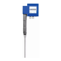
Details the process of installing the NRGT 26-2s.

Electrical Connection

Bringing Into Service

Factory Settings Adjustment

Explains how to change factory settings if needed.

Parameter Selection and Setting

Calibration Procedures

CAL.L Calibration (0% Range)

Details the steps for calibrating the lower limit (0%) of the measuring range.

Advanced Calibration and Filtering

CAL.P Calibration (>25% Range)

Explains partial filling calibration (CAL.P) as an alternative.

CAL.H Calibration (100% Range)

Details calibration at the upper limit (100%) for accuracy.

Operational Checks and Tests

Level Display Verification

Explains how to verify the level display accuracy by adjusting fluid levels.

Safety Function Testing

Describes how to test the safety function using the rotary knob.

Starting, Operation, and Testing

Operating States and Malfunctions

Malfunction Indication (Fault Codes)

Describes how malfunctions are indicated via fault codes and LEDs.

Safety Function Simulation Test

System Malfunctions and Causes

Causes of Malfunctions

Lists potential causes for system malfunctions.

Installation and Wiring Checks

Outlines checks for installation and wiring to prevent malfunctions.

Fault Code Troubleshooting

Common Application and Usage Errors

Troubleshooting Specific Issues

Taking Out of Service

Maintenance and Disposal

Related product manuals