6
Important note
n If the level probe is installed in a boiler external level
pot, the controller should be switched over to manual
control before purging the pot. Do not forget to switch
back to automatic operation after purging.
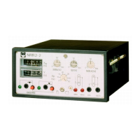
Automatic control
1. Set auto/manual switch
2 in position .
2. The green LEDs
$ indicate the mode of operation of
the controller. When the boiler load is constant, the
valve position must also be constant, i. e. the LEDs
$
should only light up occasionally. However, if under
such circumstances they light up frequently the pro-
portional band X
p
(adjustor §) must be increased.
3. If, as a result of the greater proportional band, occasio-
nally high or low-level alarm is given (red LEDs
% and
&), the proportional band must be reduced again.
Manual control
1. Set auto/manual switch
2 in position .
2. To motor valve closed: Press push button
".
3. To motor valve open: Press push button
8.
Operation
deviation “X
w
” will be + 10 %, viz 20 mm above the
adjusted set point and at full load – 10 %, viz 20 mm
below the adjusted set point. In this case the proportional
band is 40 mm.
To ensure a smooth control the proportional band X
p
(ad-
justor
§) should be chosen as large as possible. As an
initial value we recommend X
p
= 20 %.
Step 9
Adjustment of set point
The scale of the set-point adjustor “W”
3 is related to
the length of the measuring range (e. g. 200 mm length
of water-level gauge glass = 100 %. Adjust set point so
that the proportional band has the same distance to the
low level and the high level.
The set point can be determined without calculation as
follows: Raise the boiler level to the desired value. The
boiler must be operating, steam consumption zero. Then
turn setpoint adjustor “W”
3 until the error-meter “X
w
”
5 shows 0 %.
ENGLISH – continued –
Fault: The controller signals high-level alarm, although
the level in the water-level gauge glass has not reached
the high-level mark.
Remedy: The level probe is defective. Measure the
voltage between terminals 14 and 15. If the voltage is
> 10 V, replace level probe.
If faults occur that are not listed above please contact
our subsidiary or agency in your country.
Fault finding