EasyManua.ls Logo

Getronic GT915 - Engine Immobilisation Wiring; Connection Diagrams

Getronic GT915
16 pages
Print Icon
To Next Page IconTo Next Page
To Previous Page IconTo Previous Page
Loading...
4
= FUSE TO
INSERT
LEGEND:
A
8
17
9
18
1
2
10
2
1
11
3
4
12
4
8
13
5
14
6
15
7
16
B
RED - Pos. 5A
GREEN/BROWN - Pos. 4A
RED/WHITE - Pos. 14A
ORANGE/BLACK - Pos. 10A
ORANGE - Pos. 1A
PINK - Pos. 6B
BROWN - Pos. 1B
YELLOW - Pos. 3A
+15/54
IGNITION
SWITCHED LIVE
BROWN - Pos. 7A
EARTH
+12V POSITIVE
15A
FUSE
GREEN/BLACK - Pos. 2B
RED/BROWN - Pos. 11A
YELLOW/BROWN - Pos. 6A
RED/GREY - Pos. 13A
YELLOW/GREY - Pos. 16A
RED/BLUE - Pos. 12A
UNIVERSAL
CENTRAL
DOOR LOCKING
INDICATORS
GT931
ULTRASONIC
MODULE
DOORS
PIN SWITCH
MANUAL DISARMING
BY GT888
RED - Pos. 7B
BROWN - Pos. 4B
YELLOW - Pos. 8B
BLACK - Pos. 5B
AMP
AMP
WHITE - Pos. 9A
GREY - Pos. 17A
PASSIVE ENGINE
IMMOBILISATION
GREEN - Pos. 2A
BONNET
PIN SWITCH
6
8
5
7
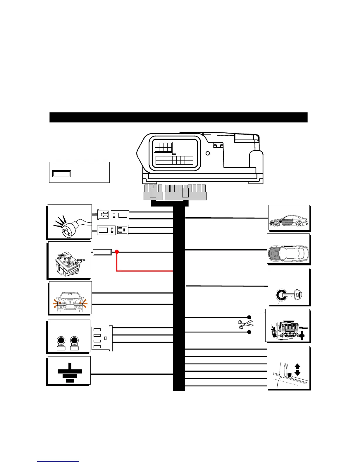
3.0 - CONNECTION DIAGRAM
- The WHITE and GREY wires (Max. capacity 7 mA) are used for the engine immobilisation
either on the diesel or petrol vehicles. Cut the ignition switched wire which supplies the
fuel pump or electrovalve (diesel vehicles). Connect the two wires one to the GREY wire
and the other to the WHITE one.
- Place the LED/RECEPTACLE on the dashboard (so that it is easily visible and accessible)
and join together the connector with the connector on the alarm loom.

Related product manuals