Do you have a question about the Geyserwise Delta T and is the answer not in the manual?
The central unit performing programmed functions and sending instructions to the pump and element.
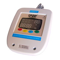
Provides system status, geyser temperature, collector temperature, pump/element status, and electricity usage.
Measures geyser temperature and acts as a thermostat, including a thermal cut-out.
Senses collector panel temperature and relays information to the control box via an extension cable.
Suitable for 220V pumped solar hot water heaters, following manufacturer instructions for other components.
Installation, maintenance, and dismantling by trained personnel only, per manual and safety instructions.
Details operating voltage, relay ratings, voltage range, ambient temperatures, and temperature ranges.
Prohibits operation outdoors, in damp rooms, or where electrical components may be dangerous.
Highlights risks of electrocution and fire due to short circuits during installation.
Manufacturer not responsible for damage from improper installation, operation, or usage.
Outlines key steps: safety, control box, display, thermostat replacement, collector probe, connections, and setup.
Crucial precautions include switching off power at DB and testing with a multimeter to ensure no current.
Choose a dry location near the isolator switch, ensuring the control box is protected from elements.
Mount in an accessible location, not reachable by children, connecting cable to the control box.
Remove existing thermostat and install the GeyserWise temperature probe with built-in thermal cut-out.
Position the probe on the return side of the collector panel at its highest point for accurate temperature measurement.
Diagram showing connections for Geyser Thermostat, Collector Probe, and Display on the control box.
Connect Live (Red), Neutral (Black), and Earth wires from the isolator switch to the control box.
Connect Live, Neutral, and Earth wires from the controller to the geyser's connector block.
Connect wires to the geyser's connector block and replace the cover to protect the electrics.
Switch on main supply at DB board, then switch on power at the isolator switch.
Connect Live, Neutral, and Earth wires from the controller to the pump, ensuring secure connections and cord grip fastening.
Shows the current temperature of the water in the geyser.
Shows the temperature of the collector panel (pumped solar systems only).
Indicates the current day of the week.
Shows the current time of day.
Indicates whether the heating element is on or off.
Indicates whether the pump is running.
Shows the status of the set timers.
Step-by-step guide to set the current day of the week using the green set and arrow buttons.
Instructions to set the current time by pressing the green set button and using arrow keys for hours and minutes.
Explains setting four maximum temperature levels applicable to different quarters of the day.
Defines solar differential and provides steps to adjust it between 7°C and 15°C.
Explains the anti-freeze function and how to set the temperature between 0°C and 10°C.
Guide to setting four on/off timers for weekdays and weekends, adjusting hours and minutes.
Procedure to remove a timer setting by setting it to 00:00 or --:--.
Enables a mode to prevent overheating when the geyser is not in use, by switching off the element and controlling the pump.
Allows manual overriding of element timers by pressing the power button once.
Details the pump indicator's function and troubleshooting hints for pumped solar systems.
Describes the element indicator's meaning when on, off, or flashing, indicating maximum temperature reached.
Explains how to view and reset the hour counter to track element usage and estimate energy consumption.
Indicates empty cylinder or thermal pocket too close to element. Actions involve checking connections and water supply.
Signifies a damaged or improperly connected geyser sensor. Requires sensor replacement or connection check.
Indicates slow heating due to leaks, faulty valves, scale, or element issues. Requires checking multiple factors.
Occurs when geyser temperature exceeds 85°C. Action is to open hot water tap to reduce temperature.
Points to poor contact or damaged cable between control box and display. Requires checking the communications wire.
Suggests faulty sensor, or extreme temperatures. Requires checking water circulation and sensors.
Indicates a faulty pump, blockages, or electrical error. Requires pump replacement, connection check, or cleaning.
Explains causes like empty cylinder or thermal pocket proximity and provides remedial actions.
Details causes of sensor failure and recommends checking connectors, wiring, and probes.
Covers causes of slow heating, including heat loss calculations and remedial actions.
Details causes for over-temperature errors (exceeding 85°C) and the action to reduce temperature.
Explains communication issues due to cable faults and recommends checking the communications wire.
Addresses overheating prevention, temperature reduction, and collector issues for pumped solar systems.
Explains pump failure causes like blockages or electrical errors, and suggests troubleshooting steps.
Discusses systems exceeding 90°C, manual reset procedures for thermostats, and MAX model thermostat features.
Explains risks during power outages, collector overheating, and system behavior upon power restoration.
Illustrates methods like Boot Lace Ferrule and Fold Back to ensure secure wire connections.
Details the fold-back wire technique for secure terminal block connections, emphasizing 2.5mm² wire and proper tightening.
Explains the function that circulates warm water to prevent freezing, recommending indirect systems for frost-prone areas.
| Voltage | 220-240V AC |
|---|---|
| Amperage | 16A |
| Power Supply | Mains Powered |
| Protection Rating | IP20 |
| Warranty | 1 Year |
| Type | Electronic Thermostat |
| Temperature Range | 0°C to 99°C |
| Features | Overheat Protection |
| Temperature Display | Digital |
| Sensor Type | NTC Sensor |