Narrow lens
After changing the dipswitch settings, make sure to push the function
switch for 2 seconds.
2
1
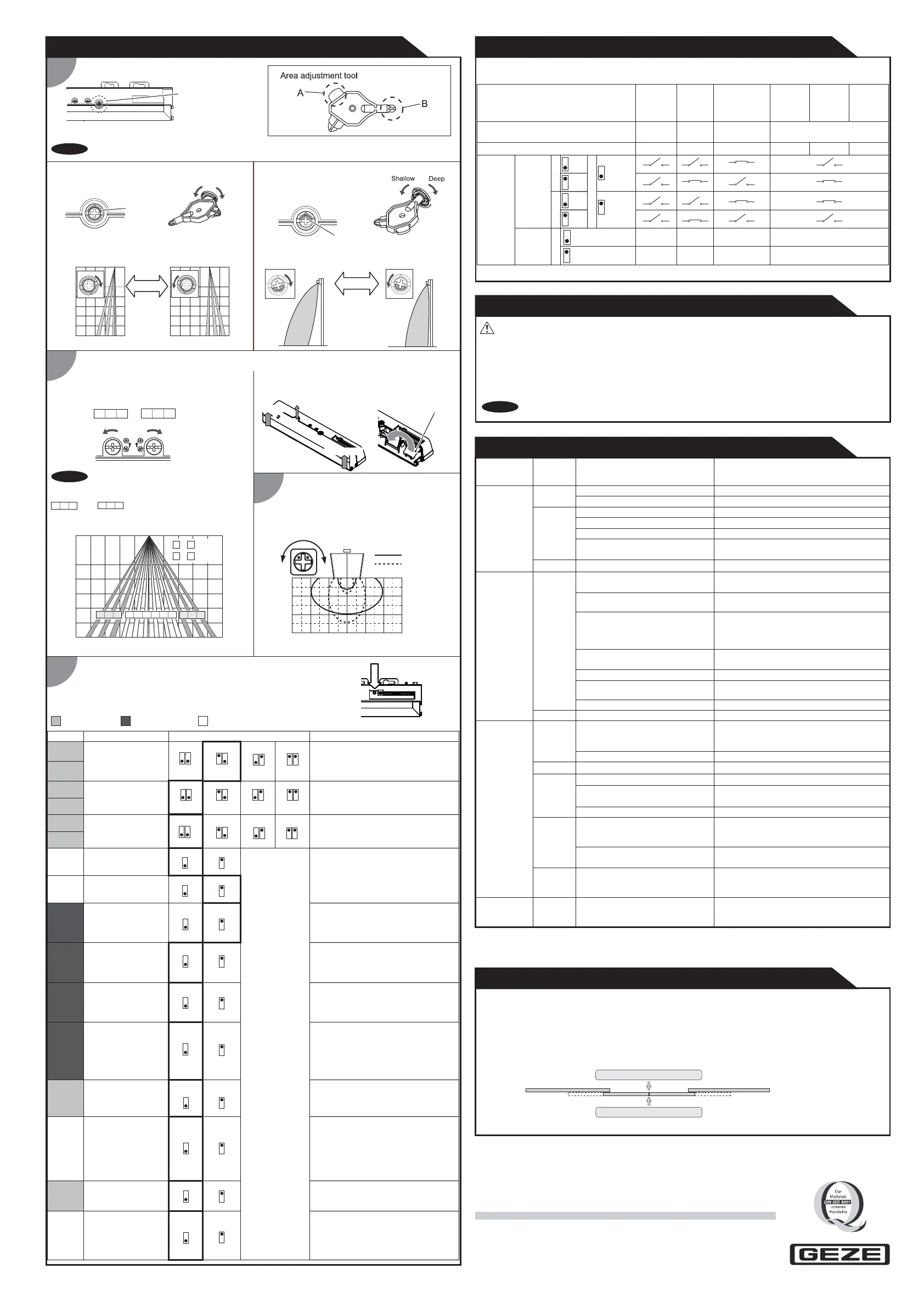
ADJUSTMENTS
Red
Area depth angle adjustment
Area width adjustment
Blue
Depth angle adjustment screw
for the AIR area
Depth angle adjustment screw
for the radar area
Use the area adjustment tool (A) as shown above
to change the area depth angle.
3
1-1AIR adjustment
2-1 AIR adjustment
1-2 Radar adjustment
Depth angle
adjustment screw
Shallow
Deep
Check the operation in the operation mode according to the chart below.
Dipswitch settings
When adjusting the 2nd row close to the door,
see Table 2 DIP-switch16 for the easier adjustment.
1. Always keep the detection window clean. If dirty, wipe the window with a damp cloth. Do not use any cleaner / solvent.
2. Do not wash the sensor with water.
3. Do not disassemble, rebuild or repair the sensor yourself, otherwise an electric shock may occur.
4. When the operation indicator blinks green, contact your installer or service engineer.
5. Only the service engineer is allowed to change the settings.
6. Do not paint the detection window.
WARNING
1. When turning the power ON, always walk-test the detection area to ensure the proper operation.
2. Do not place any objects that move or emit light in the detection area. (e.g. plant, illumination, etc.)
Make sure that the detection area does not overlap with the door/operator cover, and there is no highly
reflecting object near the detection area otherwise ghosting/signal saturation may occur.
NOTE
NOTE
NOTE
4
CHECKING
INFORM BUILDING OWNER / OPERATOR OF THE FOLLOWING ITEMS
When setting the detection area width, make sure to turn
the adjustment screws until it clicks.
resp. can only be turned off as a group.
To adjust the AIR detection area width, use the
adjustment screws as shown below.
2-2 Radar adjustment
Use the area adjustment tool (B) as shown above
to change the area depth angle.
To adjust the radar detection area width, use the
narrow lens as shown in the picture below.
push 2 seconds
2. Open
2. Open
1. Remove screw
Low
High
High
Low
Top view
High
Low
[m(feet,inch)]
Mounting height : 2.2 m (7'3")
Vertical adjustment : +35
°
Wide area
Narrow area
Status
Green
Radar
detection active
Red
Red Blinking
Blue
Entry
Outside of
detection
area
Entry into
radar area
Entry into
3rd row
Entry into
2nd row
Entry into
Lookback
(1st row)
Orange
Operating
mode
Operation indicator
AIR
detection active
Power OFF
-
None
Activation
output
Safety
N.O.
12
N.C.
Safety
+
Activation
13
GC 365 R
GC 365 SF
Safety
Safety + Activation
13
0 Hz 100 Hz 100 Hz
100 Hz0 Hz
0 Hz
0 Hz 0 Hz
*After changing the DIP-switch and/or potentiometer settings, make sure to push the function switch for
2 seconds.
AIR settings Radar settings Other settings
Contact your installer or service engineer.
Sensor failure
Wrong wiring or connection failure. Check the wires and connector.
Wrong wiring or connection failure.
Check the wires and connector.
Door operation
Operation
indicator
Possible cause
Possible countermeasures
None Wrong power supply voltage. Set to the stated voltage.
Wrong wiring or connection failure.
Fast
Green
Blinking
Signal saturation (2nd or 3rd row)
Dirty detection window Wipe the detection window with a damp cloth.
Do not use any cleaner or solvent.
Sensitivity is too low. Set the sensitivity higher.(*)
The detection area overlaps with
the door/operator cover.
Adjust the detection area to "Deep" (Outside).
Unstable
Sudden change in the detection area.
Check Table 2 DIP-switch 1 to 4.(*)
If the problem still persists, hard-reset the
sensor.(Turn the power OFF and ON again)
Slow
Green
Blinking
Check the wires and connector.
Remove highly reflecting objects from the
detection area. Or lower the sensitivity.(*)
Or change the area depth angle for AIR area.
Remove highly reflecting objects from the
detection area. Or lower the sensitivity.(*)
Or change the area depth angle for AIR area.
Setting error of DIP-switch and/or
potentiometer
Red &
Green
Blinking
Unstable
Wrong detection area positioning.
Check ADJUSTMENTS 1, 2, 3.(*)
Sensitivity is too low.
Set the sensitivity higher.(*)
Short presence timer.
Set the presence timer longer.(*)
Proper
Proper
Wrong setting of DIP-switches. Check Table 2 DIP-switch 7, 8, 12.(*)
Dirty detection window. Wipe the detection window with a damp cloth.
Do not use any cleaner or solvent.
TROUBLESHOOTING
Area depth adjustment with INFRARED FINDER (separately available)
After changing the DIP-switch and/or
potentiometer settings, make sure to push the
function switch for 2 seconds.
Proper
operation
Others Set
DIP-switch 11 to
"
ON
"
.(
*)
Waterdrops on the detection window.
The detection area overlaps with
that of another sensor.
Check Table 2 DIP-switch 5, 6.(*)
Objects that move or
emit light in the detection area.
Remove the objects.
Sensitivity is too high. Set the sensitivity lower.(*)
Installation mode is set to "ON". Set DIP-switch 16 to "OFF".(*)
Yellow
Signal saturation. (Lookback)
Slow
Green
Blinking
Set DIP-switch 9 to "Uni" and/or DIP-switch 11
to "ON".(*)
Raining or snowing.
Table 2
Adjust the radar detection area with potentiometer.
Afterwards, make sure to push the function switch for
2 seconds.
ShallowDeep
Detection area
Detection area
Or wipe the detection window with a damp cloth.
Do not use any cleaner or solvent.
To enable the presence detection, do not
enter the detection area for 10 seconds
after setting the timer.
When using more than one sensor close
to each other, set the frequency different
for each sensor.
When DIP-switch 9 is set to "Uni", this
setting enables the door to close faster
when a person walks away from the door.
When DIP-switch 10 is set to "ON", a
person wavering in the radar detection
area can be detected. This is only effective
when DIP-switch 9 is set to "Uni".
When DIP-switch 11 is set to "ON" the
actual detection area may occur smaller.
When DIP-switch 13 is set to
"Safety + Activation", the door will also
open when a person is in the AIR area.
To comply with EN 16005 and DIN 18650,
the self-monitoring has to be enabled
(position OFF).
When DIP-switch 15 is set to "ON", the
lookback (1st row) is active and looks
through the threshold.
Set DIP-switch 16 to "ON" to adjust the
2nd row. During the installation mode only
the 2nd row remains active and the
operation indicator shows yellow. After
setting the row set DIP-switch 16 "OFF".
Presence timer
Frequency
43
600 s
43
60 s
43
180 s
43
30 s
65
65
65
Setting1
Setting4
Setting3
65
Setting2
Test input
High
Bi
OFF
OFF
Safety output
Direction
A.C.M.
Immunity
N.O.
Radar output
(to door controller)
Safety
AIR output
Self monitoring
OFF
Lookback
(1st row)
OFF
Installation mode
High
7
8
Low
8
9
Uni
9
10
ON
10
11
ON
11
12
N.C.
12
13
Safety +
Activation
13
Enable
14
Disable
14
15
ON
15
16
ON
16
Low
7
Function
DIP-switch
1
DIP-switch
2
DIP-switch
3
DIP-switch
4
DIP-switch
5
DIP-switch
6
DIP-switch
7
DIP-switch
8
DIP-switch
9
DIP-switch
10
DIP-switch
11
DIP-switch
12
DIP-switch
13
DIP-switch
14
DIP-switch
15
DIP-switch
16
Set the sensitivity according to the
mounting height.
Setting
21
21
21
Low
High S-High
Sensitivity
Comment
2.0 to 3.0 m
21
Middle
2.0 to 3.0 m 2.5 to 3.2 m 3.0 to 3.5 m
Radar sensitivity
Adjust the detection area to "Deep" (Outside).
Or set DIP-switch 11 to
"
ON
"
.
(*)
ShallowDeep
1.0
(3′3")
1.0
(3′3")
00
[m(feet,inch)]
Front view
[m(feet,inch)]
0
0
2.0
(6′7")
2.0
(6′7")
1.0
(3′3")
1.0
(3′3")
3.0
(9′10")
2.0
(6′7")
N.O.
12
N.C.
-1.0
(-3′3")
4 9
1
12
~
~
:Wide
:Narrow
3.5
(11′6")
123
10 11 12
456 78 9
123
10 11 12
Width adjustment screws
Narrow
Wide
Turned off
Turned off
123
10 11 12
GC 365 R: N.O.
GC 365 SF: DIP-switch 12 has no effect
1.0(3′3")
2.0(6′7")
3.0(9′10")
0
3.0
(9′10")
2.0
(6′7")
1.0
(3′3")
03.0
(9′10")
2.0
(6′7")
1.0
(3′3")
2.0 (6′7")
3.0 (9′10")
3.5 (11′6")
Please adjust
by using the tool (B)
The delay time between Test input and
Safety output is 10 ms.
Or install in a place keeping the waterdrops off.
Use the rain-cover. (Separately available)
Proper
The detection area overlaps with
the door/operator cover.
EN 16005 DIN 18650
GEZE GmbH
Tel. : 0049 7152 203-0
Fax. : 0049 7152 203-310
www.geze.com
Material number 160272-00
Reinhold-Vöster-Stra e 21-29
ß
D-71229 Leonberg
Germany
Door does not
open when a
person enters
the detection
area.
Door opens
when no one
is in the
detection area.
(Ghosting)
Door remains
open
1. Set the DIP-switch 16 "Installation mode" to ON and confirm by pushing the function switch for 2 seconds
2. Turn the depth angle adjustment screw to the right (deep) to place the detection area away from the door.
3. Place the INFRARED FINDER on the floor until it detects the infrared curtain.
4. Slide the INFRARED FINDER as close as possible towards the door
5. Turn the depth angle adjustment screw to the left (shallow) until the INFRARED FINDER lights up.
6. Set the DIP-switch 16 to OFF and confirm by pushing the function switch for 2 seconds.
 Loading...