Do you have a question about the GEZE Powerturn Series and is the answer not in the manual?
Explains symbols and text for safety warnings about injury or damage.
Details symbols for important information, concepts, and workflow optimization.
Details critical safety measures to follow during installation and operation.
Covers installation requirements, cable handling, and environmental considerations.
Emphasizes safety precautions for operating the drive and securing the workspace.
Outlines checks for securing components and verifying system functionality.
Explains the setup and parameterization for the GC 338 safety sensor strip.
Details the connection and configuration of the GC 334 safety sensor.
Covers the master/slave setup and parameterization for GC 335 safety sensors.
Details the setup and parameterization for using a key switch as an authorized sensor.
Covers the setup and parameterization of the GC 302 R radar movement detector.
Explains the configuration for a push button with a floating NO contact.
Details the setup for the GC 302 R as an external contact sensor.
Explains the configuration of a push button as an external contact sensor.
Explains the functions and operation of radio channels FK1 and FK2.
Details the procedure for installing the WRB-5 radio board.
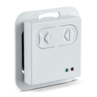
Explains the connection and function of the Mechanical Programme Switch (MPS).
Covers using configurable inputs for 2-leaf or 1-leaf open modes.
Details using configurable inputs for sabotage monitoring of enclosures.
Explains connecting an emergency lock switch to configurable inputs.
Describes connecting additional NO contacts as sensors.
Explains pushbutton configuration for door opening and closing functions.
Details using inputs for stop push buttons or sensor strips.
Explains using configurable inputs for resetting the control unit.
Covers double push button use for 1-leaf or 2-leaf door opening.
Explains the setup and functions for configurable output PA1.
Explains the setup and functions for configurable output PA2.
Details the use and modes of the Mechanical Programme Switch (MPS).
Explains setting operation modes via external push buttons or switches.
Describes how to change the drive's operation mode.
Details the configuration for automated active leaf with passive leaf door closer.
Explains the connection and setup for two automated door leaves.
Describes establishing RS485 communication between drives.
Details the procedure for connecting the drive to the mains power supply.
Details the integration of the lintel smoke switch in Powerturn F/R.
Describes hold-open systems with door closer and magnetic lock.
Details the setup and connection of the mounting plate with feeder.
Outlines the requirements and steps for initial drive commissioning.
Explains the process and observations for the drive's teaching run.
Details the step-by-step procedure for teaching a 1-leaf system.
Details the step-by-step procedure for teaching a 2-leaf system.
Explains setting door forces and speeds for optimal performance.
Details the operation and connection of the ST220 service terminal.
Explains how to connect the ST220 service terminal to the control board.
Outlines the structure and access to the ST220 service menu.
Explains setting and selecting the drive's operation mode via ST220.
Details parameters for setting door width, weight, and mounting type.
Covers setting speeds, forces, and obstacle detection parameters.
Details configuration of input and output signals for various functions.
Explains how to view current values, error memory, and system data.
Explains how to initiate the drive's teaching procedure.
Explains how faults are displayed on the ST220 and DPS interfaces.
Details how fault groups are indicated via service button LEDs.
| Opening Angle | Adjustable, up to 110° |
|---|---|
| Operating Voltage | 24 V DC |
| Max Door Leaf Width | 1600 mm |
| Power Supply | 230 V AC, 50 Hz |
| Fire Protection | Yes |
| Manual Use | Yes |
| Power Consumption | Approx. 150 W |
| Hold-open Time | Adjustable |
| Max. Leaf Width | 1600 mm |
| Closing Speed | Adjustable |
| Opening Speed | Adjustable |