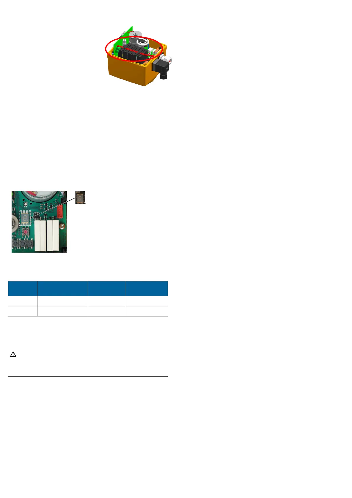
3 Internal cable routing External battery
Use the cable glands provided to insert the cable
(in red on graphic)
for the control signal. Ensure
that the cable is fixed along the contact
protection by the clamps provided to avoid the
cable from further movements. Avoid excess
length of the battery cable.
Cable specifications:
1x2 wire, AWG 18-16, UL/cUL AWM 4486 min.
125°C 1000V, outside diameter 8-13mm (cable
glands)
4 Test functioning of the fail-safe return unit
Functioning test with and without battery:
Apply power to the actuator and move into position OPEN. Remove power to
the actuator. Actuator moves after about 5s to CLOSE position (or reversed,
depending on the setting of the switch).
4. Put the cover back in place and fasten it with the 4 screws.
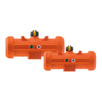
5 Error message
An error can triggers the following:
The 7-segment display on the main board illuminates; see illustration
below.
The ready-to-operate signal will be off (terminals 5,6 NO contact)
LED flashes yellow (except in case of power outage)
Assignment of error codes for error messages
If the fail-safe return unit PCB is installed, the following error codes can be
displayed:
Error code Description
Signal „Ready-
to-operate“
EA response
L
Battery voltage < 50% Yes Normal operation
A
Battery faulty No Normal operation
For further error codes of the main board, see instruction manual of the electric actuator
type EA15.
Acknowledge error message
Check the cause of fault, if necessary, carry out relevant maintenance.
NOTE!
The message can be eliminated while the supply voltage is still connected
or the actuator is briefly disconnected from the mains voltage (does not
work with cycle monitoring).
Error can be acknowledged via the „SET“button on the main board.