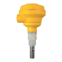
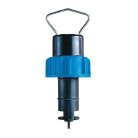
3-2850-61, 3-2850-62, 3-2850-63
with Universal adapter
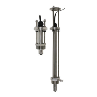
3-2850-51, 3-2850-52
with ¾-in. adapter
3-2850-51-XX, 3-2850-52-XX
Integral System
Signet 2850 Conductivity/Resistivity Sensor Electronics
3-2850.090-1 Rev. K 03/15
*3-2850.090-1*
English
Operating Instructions
Description
Table of Contents
Dimensions
• English
• Deutsch
• Français
• Español
• Italiano
• Signet 2850 Conductivity/Resistivity Sensor Electronics provides either a two-wire
4 to 20 mA output or Digital (S
3
L) format.
• The 4 to 20 mA output models provide eight ranges for each electrode cell constant,
plus the ability to invert each range.
• The EasyCal feature allows the devices to automatically recognize standard
conductivity test solution values for simple fi eld calibration.
• The Conductivity Sensor provided with integral systems will have its custom cell
constant information programmed into the electronics at the factory to provide a
2% sensor accuracy. See page 6 for details.
2850-51, -52 Integral mount 2850-61, -62, -63 Universal mount
85 mm
3.34 in.
95 mm
3.74 in.
82 mm
3.24 in.
95 mm
3.74 in.
Description ............................................................................................ 1
Dimensions ........................................................................................... 1
Warranty Information ............................................................................ 2
Product Registration ............................................................................. 2
Safety Information................................................................................. 2
Specifi cations........................................................................................ 2
Conductivity Sensor Dimensions .......................................................... 3
Operating Range Chart......................................................................... 3
In-Line Installation................................................................................. 4
Tank Installation .................................................................................... 4
4 to 20 mA Wiring ................................................................................. 5
Digital (S
3
L) Wiring ................................................................................ 5
Dual Input Wiring (Dual Digital (S
3
L) Output) ........................................ 5
Cell Constant Selection ........................................................................ 6
Range Selection for 4 to 20 mA Output ................................................ 7
Calibration............................................................................................. 8
EasyCal ................................................................................................ 8
Dual Input Calibration ........................................................................... 8
Maintenance ......................................................................................... 9
Troubleshooting .................................................................................... 9
Electronic Certifi cation ........................................................................ 10
Ordering Information ........................................................................... 12