EasyManua.ls Logo

GF Signet 9900-1BC User Manual

GF Signet 9900-1BC
28 pages
To Next Page IconTo Next Page
Page #1 background imageLoading...
Page #1 background image
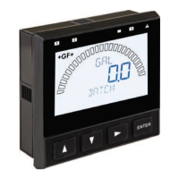
Signet 9900-1BC Batch Controller System
3-9900-1BC.090-1 Rev. 6 05/20 English
*3-9900-1BC.090*
Panel Mount
Product Manual
Look for the Quick Start icon to
quickly set up your new 9900-1BC.
The Signet 9900-1BC Batch Controller is compatible with the Signet models
515 (8510), 525, 2536 (8512), 2537 and 2540 paddlewheel  ow sensors,
models 2551 and 2552 insertion magmeters, 2580 FlowtraMag meter and
models 2000, 2507, and 2100 in-line  ow sensors.
Your new 9900-1BC Batch Controller system includes the following items:
Signet 9900 Transmitter (3-9900-1P)
Signet Relay Module (3-9900.393)
Signet Batch Module (3-9900.397)
Note:
Batch Module requires Generation II or later, 9900 transmitter.
Verify 9900 Transmitter generation under the OPTIONS Menu.
English
Deutsch
Français
Español
中文
English
Compatibility
Description
CAUTION:
In the event of a power failure, please review
the batch settings before resuming a batch.
Failure to do so could result in an over ll of
the container.
Question and Answer IconNeed help?

Do you have a question about the GF Signet 9900-1BC and is the answer not in the manual?

GF Signet 9900-1BC Specifications

General IconGeneral
Output Current4-20 mA
Communication ProtocolModbus RTU
DisplayLCD
Storage Temperature-20 to 85 °C (-4 to 185 °F)
EnclosureNEMA 4X

Summary

Warranty, Registration, and Safety

Safety Information

Provides crucial safety instructions for operating the 9900-1BC Batch Controller safely.

Dimensions and Installation

Installation Procedures

Guides users through the process of installing the 9900-1BC Batch Controller, including panel mounting.

Modules: Batch and Relay

Modules Overview

Explains the function and wiring of the Batch Module and Relay Module.

Batch Module Functionality

Describes how to convert the 9900 Transmitter to a Batch Controller using the Batch Module.

Relay Module Capabilities

Details the Relay Module's capabilities, including dry-contact relays for expanded output control.

Terminal Identification

Software Requirements and Warnings

Software Considerations

Warns about potential issues with 4-20mA loop controlled devices in batch control.

Important Software Requirement

Highlights the requirement for Generation II software for proper batch module operation.

Wiring Guidelines

Sensor Wiring Diagrams and Notes

Sensor Wiring Diagrams

Illustrates sensor wiring diagrams for various Signet flow sensors.

Wiring: Sensor, Power, and Batch Module

Power Wiring Options

Illustrates power wiring for stand-alone applications and connection to 4-20 mA devices.

Batch Module Wiring

Details how to wire external buttons or keypads to remotely control the Batch Module.

Open Collector Output Configuration

Open Collector Wiring

Explains the features and wiring configurations (NPN/PNP) for the Open Collector output.

Relay Module Wiring and Basic Modes

Relay Module Wiring

Shows how to wire the Relay Module and explains the function of NO/NC contacts.

Advanced Relay Mode Settings (Part 1)

Advanced Relay Mode Settings (Part 2)

TWO STG – Two Stage Mode

Manages mainline and bypass relays for two-stage filling to prevent overfilling.

Operation: Front Panel Overview

Menu Navigation Keys

Explains the function of the UP, DOWN, RIGHT, and ENTER keys for menu operation.

System Setup and Menu Navigation

System Setup: Menu Navigation Steps

Outlines the step-by-step process for entering menus, editing values, and saving changes.

Menu System Overview and Error Handling

Password System Explained

Details the password system (STD and CODE) for accessing settings.

VIEW Mode: Batch Running Display

Stopping an Active Batch

Instructions on how to stop an active batch using the ENTER button.

VIEW Mode: Batch Stopped Operations

Batch Control and Selection

Covers starting, resuming, cancelling, and selecting batches.

Batch Size Adjustment

Explains overriding and manual batch topping off for size adjustment.

Menu Configuration: CAL and INPUT

CAL Menu Configuration

Explains settings related to calibration, including K-Factor and T-Factor.

Calibration Factors: K-Factor & T-Factor

Sets calibration factors for flow sensor pulse conversion.

Volume Calibration and Overrun Compensation

Guides calibration and sets overrun compensation.

INPUT Menu Configuration

Details configuration settings for input parameters like sensor type and batch size.

Menu Configuration: INPUT and LOOP

INPUT Menu: Mode and Signal Settings

Covers mode selection, signal handling, and batch type configuration.

LOOP Menu Configuration

Explains configuration options for the 4-20 mA output loop.

RELAY Menu Configuration

Relay Modes: MULTIPLE and TWO STAGE

OPTION Menu Settings

Error Messages and Alarm Handling

Calibration Procedures

Volume Calibration Procedure

Step-by-step guide for performing volumetric calibration to determine K-Factor.

Related product manuals