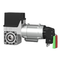
The GfA ELEKTROMAT TSE 5.24 WS-25,40 (Model: 10003805 00012) is a drive unit designed for vertically moving doors, intended for indoor use. It requires protection against moisture and aggressive environmental conditions. The drive unit is not suitable for hazardous areas, and its technical specifications must not be exceeded to ensure safe operation.
Function Description
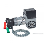
The drive unit facilitates the vertical movement of doors. For doors requiring protection against dropping, a separate safety brake is necessary. The system includes a limit switch for defining the final open and close positions of the door. It supports different operating modes, including "Hold to run OPEN," "Hold to run CLOSE," "Self hold OPEN," and "Hold to run CLOSE," selectable via a switch. The T801 component features a potential-free NO contact that closes when the final OPEN limit position is reached, providing a message indicating the door is open. Emergency manual operation is provided via a rapid hand chain operator, designed for opening or closing the door without power supply. This operation interrupts the control voltage, and electrical operation is not possible during emergency manual operation.
Important Technical Specifications
- Output Speed: 24 rpm
- Output Torque: 50 Nm (with a specification of 50 Nm according to EN 60335-2-103)
- Output / Hollow Shaft: 25.40 mm
- Series: KG 50
- Limit Switch Range: 20 (maximum revolutions of the output / hollow shaft)
- Supply Voltage: 1N~ 230 V
- Operating Current: 3.50 A
- Operating Frequency: 50 Hz
- Power Factor cos φ: 0.99
- Safety Circuit: 24 V
- Degree of Protection: IP 65
- Temperature Range: -10 / +40 (+60) °C (When using a temperature range of +40°...+60°C, half of maximum cycles per hour should be used.)
- Operating Sound Pressure Level: < 70 dB(A)
- Cycles per Hour: 9 (2.7) h⁻¹ (Specification in () according to EN 60335-2-103.)
- Max. Holding Torque: 200 Nm
- Max. Load: 2500 N
- Manual Force Emergency Manual Operation: 92 N
- Maximum Switching Current (Message door OPEN): 24V DC 0.2 A
Usage Features
- Installation: The drive unit requires self-locking connection elements with a minimum strength of 800 N/mm² (8.8). The hole diameter must be fully utilized, and adequately dimensioned washers should be used for elongated holes. Keys are used to connect to the door shaft, and it's crucial to thoroughly grease the door shaft before mounting the keys. The drive unit must be attached without hitting the gearbox with a hammer to prevent stalling. All M8 connection elements on the drive should be tightened to 25 Nm.
- Electrical Installation: Requires a single-pole automatic circuit breaker with a maximum of 10 A for protection. Connection to the indoor installation must be via an all-pole disconnector unit ≥ 10A (e.g., plug connection CEE, mains switch) in accordance with EN 12453. The control unit should only be installed indoors.
- Limit Switch Adjustment: The limit switches define the final OPEN and CLOSE positions. Adjustment involves using the OPEN pushbutton to open the door to the desired final limit position, then rotating the cam of the OPEN limit switch S3 to the middle of the tappet and tightening its screw. Fine adjustment can be made by checking the door position after correction. The CLOSE limit position is adjusted similarly.
- Control Device Connection: The manual provides diagrams for connecting control devices, including three-push button configurations and options for key switches with STOP buttons or slack-rope switches.
- Emergency Manual Operation: Activated by pulling a red handle to switch on, and pulling a green handle to switch off. The chain is used to open or close the door. It is critical to ensure a secure position and to only operate the drive unit with a brake, carrying out the emergency manual operation against the closed brake. The door should not be moved beyond the final limit positions during this operation.
Maintenance Features
- Commissioning/Inspection: After installation, all covers must be installed.
- Gearbox: Check for oil loss (a few drops are negligible) and protect the output shaft permanently against corrosion.
- Mounting: Verify that all connection elements (consoles, torque mounts, screws, locking rings, etc.) are secure and in proper condition.
- Electrical Wiring: Inspect connection cables and cabling for damage or crushing. Ensure screw connections and plug connections are properly fitted with good electrical contact.
- Emergency Manual Operation: Check the function with the power disconnected, performing the check only between the final limit positions.
- Limit Switch: Verify the final limit positions by fully opening and closing the door.
- Drive Unit: It is recommended to engage a qualified engineer to check the drive unit annually. Shorter inspection intervals should be applied for frequently operated doors. All applicable regulations and standards must be observed.
Disposal
- Packaging: Dispose of packaging material according to local legal regulations or recycle it.
- Old Devices: Dispose of old devices properly according to local legal regulations. GfA products can be returned free of charge, marked as "old devices."
- Gearbox: The gearbox contains oil and must be disposed of properly according to local legal regulations to prevent environmental damage.
The product complies with various directives and regulations, including the Machinery Directive 2006/42/EC, EMC Directive 2014/30/EU, and RoHS Directive 2011/65/EU (for EU markets), and the Supply of Machinery (Safety) Regulations 2008, Electromagnetic Compatibility Regulations 2016, and Restriction of the Use of Certain Hazardous Substances in Electrical and Electronic Equipment Regulations 2012 (for UK markets). It adheres to standards such as EN 12453, EN 60335-2-103, EN 61000-6-2, and EN 61000-6-3.