Do you have a question about the GFA TS 971 Series and is the answer not in the manual?
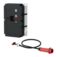
Details on connecting the power supply to the control unit.
Procedure for setting the door's OPEN and CLOSE limit positions.
Procedure for setting the door's OPEN and CLOSE limit positions for NES.
Connection details for the external power supply.
Wiring diagram and function of the emergency stop input.
Configuration for the automatic closing function.
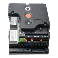
Wiring for external control devices like push-buttons.
Connection and types of photo cells used.
Wiring and function of light curtain safety systems.
Connection for the radio receiver module.
Wiring for external pull switches.
Connection for the intermediate stop function.
Wiring for traffic light indicators.
Connection for the magnetic brake system.
Diagrams for connecting spiral cables to safety edges.
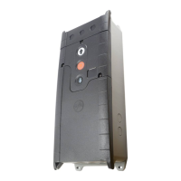
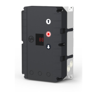
Overview of the WSD door-module and its components.
Step-by-step guide for teaching in the WSD door-module.
Final checks and connections for electrical installation.
Description of various door operating modes available.
Setting the direction of the drive unit's rotation.
Setting the OPEN final limit position with coarse adjustment.
Setting the CLOSE final limit position with coarse adjustment.
Fine adjustment of the OPEN final limit position.
Fine adjustment of the CLOSE final limit position.
Adjusting the pre-limit switch for safety edge functionality.
Setting an intermediate open position for the door.
Configuring the switching point for relay 1.
Configuring the switching point for relay 2.
Configuration of safety devices and spiral cable.
Settings for safety edge activation in the pre-limit zone.
Adjusting overrun correction parameters for the DES system.
Setting and configuring the automatic closing feature.
Advanced settings for the photo cell function.
Configuration of the door's reversing function.
Settings for pull switch or radio receiver operation.
Configuration of relay function for output X20.
Configuration of relay function for output X21.
Settings for the intermediate open function.
Monitoring door force for safety compliance.
Handling photo cell interruptions for safety.
Monitoring door travel time for safety.
Configuration of door safety switch inputs.
Settings related to automatic door opening.
Adjusting the duration of door reversing.
Setting the door's OPEN speed.
Setting the door's CLOSE speed.
Adjusting the CLOSE speed for specific opening heights.
Setting the point where CLOSE speed changes.
Configuring the OPEN acceleration ramp.
Configuring the CLOSE acceleration ramp.
Configuring the OPEN deceleration ramp.
Configuring the CLOSE deceleration ramp.
Setting the slow crawling speed for OPEN/CLOSE.
Selecting the manufacturer of compatible radio transmitters.
Functions related to the radio receiver.
Setting the maintenance cycle counter preselection.
Defining actions when the maintenance cycle count reaches zero.
Reading the cycle counter data.
Displaying information about the last recorded faults.
Reading the data counter information.
Displaying the control's software version.
Procedure for resetting all control settings to factory defaults.
Details on the safety edge input and detection.
Display codes for faults, their causes, and corrections.
| Category | Control Panel |
|---|---|
| Input Voltage | 24 VDC |
| Operating Temperature | -10°C to +55°C |
| Storage Temperature | -20°C to +70°C |
| Series | TS 971 |
| Communication | RS-485 |