Do you have a question about the GFA ELEKTROMATEN TS 971 and is the answer not in the manual?
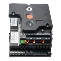
Instructions for the electrical setup, including connections and components.
Diagram illustrating the wiring of different connection cables.
Step-by-step guide for executing the electrical installation process.
Detailed instructions for connecting the mains power supply.
Specifics on how to connect the mains power to the control unit.
Final steps and checks for the electrical installation.
Procedure for quick adjustment of limit switches using DES mode.
Method for fast adjustment of limit switches using NES mode.
Wiring diagram for connecting an external power supply.
Instructions for connecting an emergency stop button.
Setup for the automatic closing function (On/Off).
Connection details for various control devices.
Wiring and setup for photo cell sensors.
Wiring and setup for light curtain sensors.
How to connect an external radio receiver.
Wiring instructions for a rope-pull switch.
Configuration for the intermediate open door position.
Connection details for function relays X20 and X21.
Guidelines for connecting safety edge systems and door safety switches.
Information on the 'WSD' wireless safety device.
Connecting an electrical safety edge to the WSD module.
Connecting System 1 optical safety edge to WSD module.
Connecting System 2 optical safety edge to WSD module.
Connecting a door safety switch to the WSD module.
Procedure to teach-in the WSD door module.
Final steps for the electrical installation of accessories.
Settings for selecting and configuring door operating modes.
Adjusting the open, closed, and pre-limit positions.
Configuration of various door operational functions.
Setting up and adjusting safety-related functions.
Parameters related to DU/FI drive unit settings.
Description of extended and advanced door functionalities.
Setting and managing the maintenance cycle counter.
Accessing and reading stored information from the memory.
Procedure to reset all settings to factory defaults.
Detailed information on the door safety switch functionality.
Overview and types of safety edge systems supported.
Instructions for correctly installing the spiral cable.
Powering external devices using the 24V DC terminal.
Connecting mains power and external supply lines.
Functionality for enabling/disabling automatic closing.
Description of connections for control devices.
Description of photo cell and light curtain operations.
Functionality of pull switches and radio receivers.
Details on using the integrated internal radio receiver.
Procedure for teaching-in handheld radio transmitters.
Methods for deleting individual or all transmitters.
Control of the intermediate open position for the door.
Description of potential-free relay contact functions.
System for monitoring door forces for safety.
System for monitoring door run times for safety.
Information on the UBS pluggable connection technology.
Adjusting the reversing time for safety edge operation.
A comprehensive list of error codes and their troubleshooting measures.
| Type | Control Unit |
|---|---|
| Model | TS 971 |
| Manufacturer | GFA ELEKTROMATEN |
| Supply voltage | 230 V AC |
| Control voltage | 24 V DC |
| Frequency | 50/60 Hz |