Do you have a question about the GFA DC 8010 and is the answer not in the manual?
Explains danger, warning, caution, and notice symbols used in the manual.
Defines the intended audience for the installation instructions.
Details the intended application and limitations of the door control unit.
Provides essential safety guidelines for installation and operation.
Lists technical specifications, dimensions, electrical data, and environmental limits.
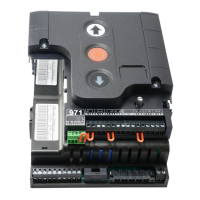
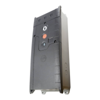
Identifies and describes the components and terminals of the control unit.
Explains the meaning of symbols and displays on the control unit.
Details the types and specifications of fuses used in the control unit.
Instructions for wiring the digital limit switch (DES) to the control unit.
Provides guidance on connecting the motor to the door control unit.
Table specifying appropriate cable sizes for AC and VFD motors.
Instructions on how to select and set the operating voltage using a jumper.
Details how to connect the control unit to the mains power supply.
Explains connecting devices requiring 24V DC power.
Instructions for connecting electrical, pneumatic, and optical safety edges.
Details connecting a door safety switch for pass doors or slack-rope switches.
Instructions for connecting an emergency stop switch.
How to connect a switch to control the automatic closing function.
Connecting external control devices like pushbuttons or keypads.
Instructions for connecting reflective or through-beam photocells.
Connecting radio receivers or pull switches for remote or manual activation.
Connecting a switch for setting an intermediate door position.
Connecting devices like traffic lights via potential-free relay contacts.
Specific instructions for connecting traffic lights to X20/X21.
Connecting and controlling magnetic brakes for specific door types.
Selecting the operational mode based on safety devices and control inputs.
How to adjust the motor's direction of rotation.
Basic adjustments to the OPEN and CLOSE limit positions.
Detailed adjustments for OPEN, CLOSE, and safety edge pre-limit positions.
Setting a specific intermediate open position for the door.
Defining when relays X20/X21 should activate based on door position.
Activating or deactivating the safety edge functionality in the pre-limit zone.
Setting the time delay for automatic door closing after it has opened.
Configuring how photocell activation affects automatic closing.
Setting the maximum number of automatic reversals allowed for the door.
Defining the door's response to radio or pull switch commands.
Configuring the output signals (lights, contacts) for relays X20 and X21.
Assigning control devices to activate the intermediate open function.
Activating and configuring force monitoring for safety against entanglement.
Setting a specific position to deactivate the photocell, avoiding false triggers.
Adjusting the duration of the door's reversal when an obstacle is detected.
Adjusts the door's opening speed.
Adjusts the door's closing speed.
Sets closing speed above a specific height.
Defines a position for higher closing speed.
Adjusts acceleration time for opening.
Adjusts acceleration time for closing.
Adjusts deceleration time for opening.
Adjusts deceleration time for closing.
Adjusts the final slow-down speed before reaching limits.
Sets the number of cycles before a maintenance reminder.
Defines actions (display, mode change) when maintenance is due.
Displays the total number of door cycles.
Shows the last recorded fault codes for diagnostics.
Shows door cycles since the last programming adjustment.
Displays the software version of the control and motor.
Instructions for resetting the control to default settings or using the GfA-Stick.
Explains fault codes and their corrections for various systems.
Outlines essential tasks for annual maintenance of the door control.
| Brand | GFA |
|---|---|
| Model | DC 8010 |
| Category | Control Unit |
| Language | English |