10
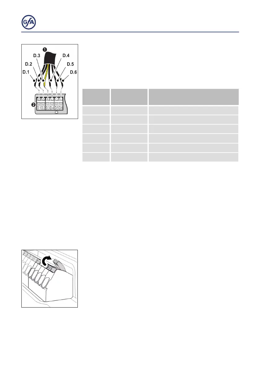
2. Attaching the connecting cable to the DC 8010
▪ The wires and terminals are colored. Connect the wires of
the DES connecting cable (1) to the matching color of the
terminals D.1 to D.6 (2).
Terminal
Color Wire/
Terminal
Function
D.1 black Safety circuit, +24V
D.2 brown Channel B (RS485)
D.3 red Ground
D.4 orange Channel A (RS485)
D.5 yellow Safety circuit
D.6 green Supply voltage 8V DC
5.3 Connecting motor to door control
The following explains how to connect the motor to the
door control. A distinction is made between 3
~ and 2~ door
drive units. The required cable AWG depends on the door
drive unit. Choose from the table on page 13. The length of the
cable should not exceed 98,4 ft (30 m).
Terminal connections
Unless otherwise described, each terminal is only suitable for
one wire.
▪ Push the clamp upwards to open the terminal.
▪ Remove 0.5“ (12 mm) of the isolation of the wire.
▪ Insert the stripped wire and push the clamp down to close
the terminal.