11
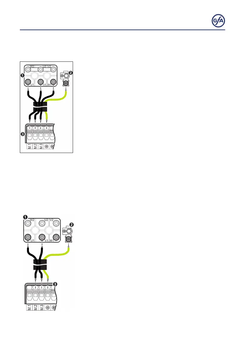
Connecting the 3~ door drive unit
▪ You need a 4 conductor cable including ground. Select the
cable AWG based on the table „Motorcable conductors size“
on the following page.
▪ Remove the cover of the terminal box on the motor of the
door drive unit.
▪ Remove the terminal cover.
▪ Connect terminals M1 to M3 (3) to the terminal board of the
motor (1) as follows:
▪ Terminal M1 to phase U1
▪ Terminal M2 to phase V1
▪ Terminal M3 to phase W1
▪ Connect the ground terminal of the DC 8010 (3) to the
grounding screw (2).
▪ Replace the cover of the terminal box and the terminal cover.
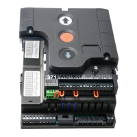
Connecting the 2~ door drive unit
▪ You need a 3 conductor cable including ground. Select the
cable AWG based on the table „Motorcable conductors size“
on the following page.
▪ Remove the cover of the terminal box on the motor of the
door drive unit.
▪ Remove the terminal cover.
▪ Connect terminals M2 and M3 (3) to the terminal board of the
motor (1) as follows:
▪ Terminal M2 to phase U1
▪ Terminal M3 to phase V1
▪ Connect the ground terminal of the door control (3) to the
grounding screw of the door drive unit (2).
▪ Replace the cover of the terminal box and the terminal cover.