Chapter 5 Parameters
VFD-E Series
Revision August 2006, 01EE, SW--PW V1.03/CTL V2.03 5-77
07.14 Motor PTC Overheat Protection Level Unit: 0.1
Settings 0.1~10.0V Factory Setting: 2.4
When the motor is running at low frequency for a long time, the cooling function of the motor
fan will be lower. To prevent overheating, it needs to have a Positive Temperature Coefficient
thermoistor on the motor and connect its output signal to the drive’s corresponding control
terminals.
When the source of first/second frequency command is set to AVI LWZLOO
GLVDEOHWKHIXQFWLRQRIPRWRU37&RYHUKHDWSURWHFWLRQLH3UFDQQRWEHVHWWR
If temperature exceeds the setting level, motor will be coast to stop and
is
displayed. When the temperature decreases below the level of (Pr.07.15-Pr.07.16) and
stops blinking, you can press RESET key to clear the fault.
3URYHUKHDWSURWHFWLRQOHYHOPXVWH[FHHG3URYHUKHDWZDUQLQJOHYHO
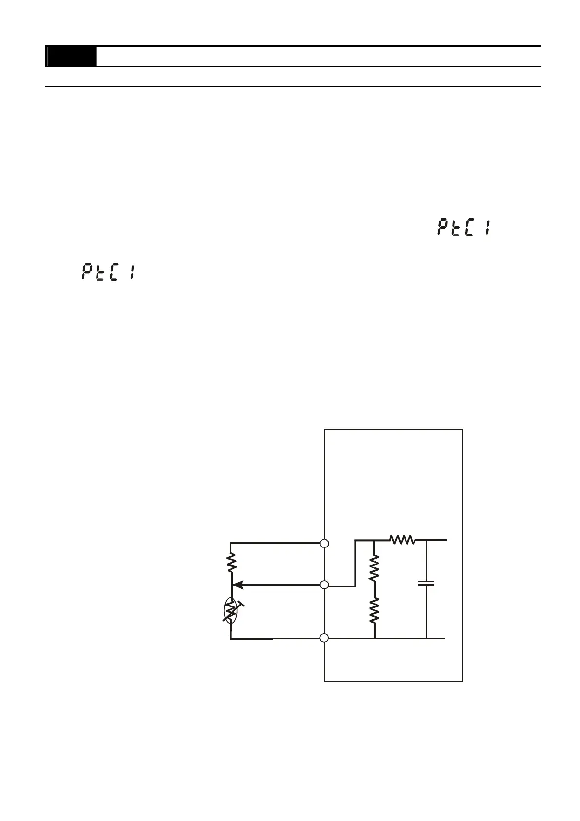
7KH37&XVHVWKH$9,LQSXWDQGLVFRQQHFWHGYLDUHVLVWRUGLYLGHUDVVKRZQEHORZ
1. The voltage between +10V to ACM: lies within 10.4V~11.2V.
2. The impedance for AVI is around 47kӨ.
3. Recommended value for resistor-divider R1 is 1~20kӨ.
4. Please contact your motor dealer for the curve of temperature and resistance value
for PTC.
VI
CM
+10V
PTC
VFD-E
47k
Ө
resistor-divider
R1
internal circuit


 To Next Page
 Loading...