Chapter 5 Parameters
VFD-E Series
5-78 Revision August 2006, 01EE, SW--PW V1.03/CTL V2.03
Refer to following calculation for protection level and warning level.
1. Protection level
Pr.07.14= V
+10
* (R
PTC1
//47K) / [R1+( R
PTC1
//47K)]
2. Warning level
Pr.07.16= V
+10
* (R
PTC2
//47K) / [R1+( R
PTC2
//47K)]
3. Definition:
V+10: voltage between +10V-ACM, Range 10.4~11.2VDC
RPTC1: motor PTC overheat protection level. Corresponding voltage level set in
Pr.07.14, RPTC2: motor PTC overheat warning level. Corresponding voltage level set
in Pr.07.15, 47kӨ: is AVI input impedance, R1: resistor-divider (recommended value:
1~20kӨ)
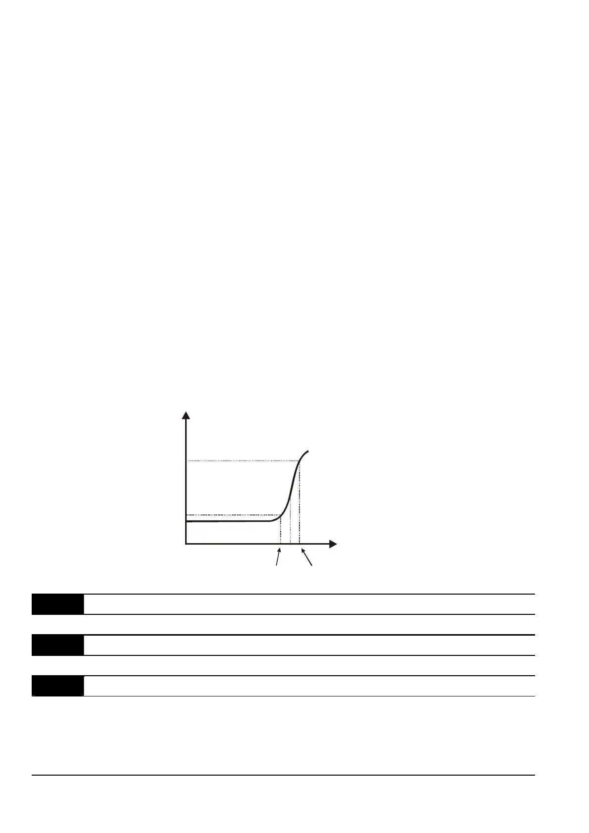
Take the standard PTC thermistor as example: if protection level is 1330Ө, the voltage
between +10V-ACM is 10.5V and resistor-divider R1 is 4.4kӨ. Refer to following calculation
for Pr.07.14 setting.
1330//47000=(1330*47000)/(1330+47000)=1293.4
10.5*1293.4/(4400+1293.4)=2.38(V) Ѝ2.4(V)
Therefore, Pr.07.14 should be set to 2.4.
550
1330
temperature ( )
ദ
resistor value ( )
˖
Tr
Tr-5
ദ
Tr+5
ദ
07.15 Motor PTC Overheat Warning Level Unit: 0.1
Settings 0.1~10.0V Factory Setting: 1.2
07.16 Motor PTC Overheat Reset Gh Level Unit: 0.1
Settings 0.1~5.0V Factory Setting: 0.6
07.17 Treatment of the motor PTC Overheat
Factory Setting: 0
Settings 0 Warn and RAMP to stop
1 Warn and COAST to stop
2 Warn and keep running


 To Next Page
 Loading...