Appendix B Accessories
VFD-E Series
B-22 Revision August 2006, 01EE, SW--PW V1.03/CTL V2.03
B.10.3 Profibus Communication Module (CME-PD01)
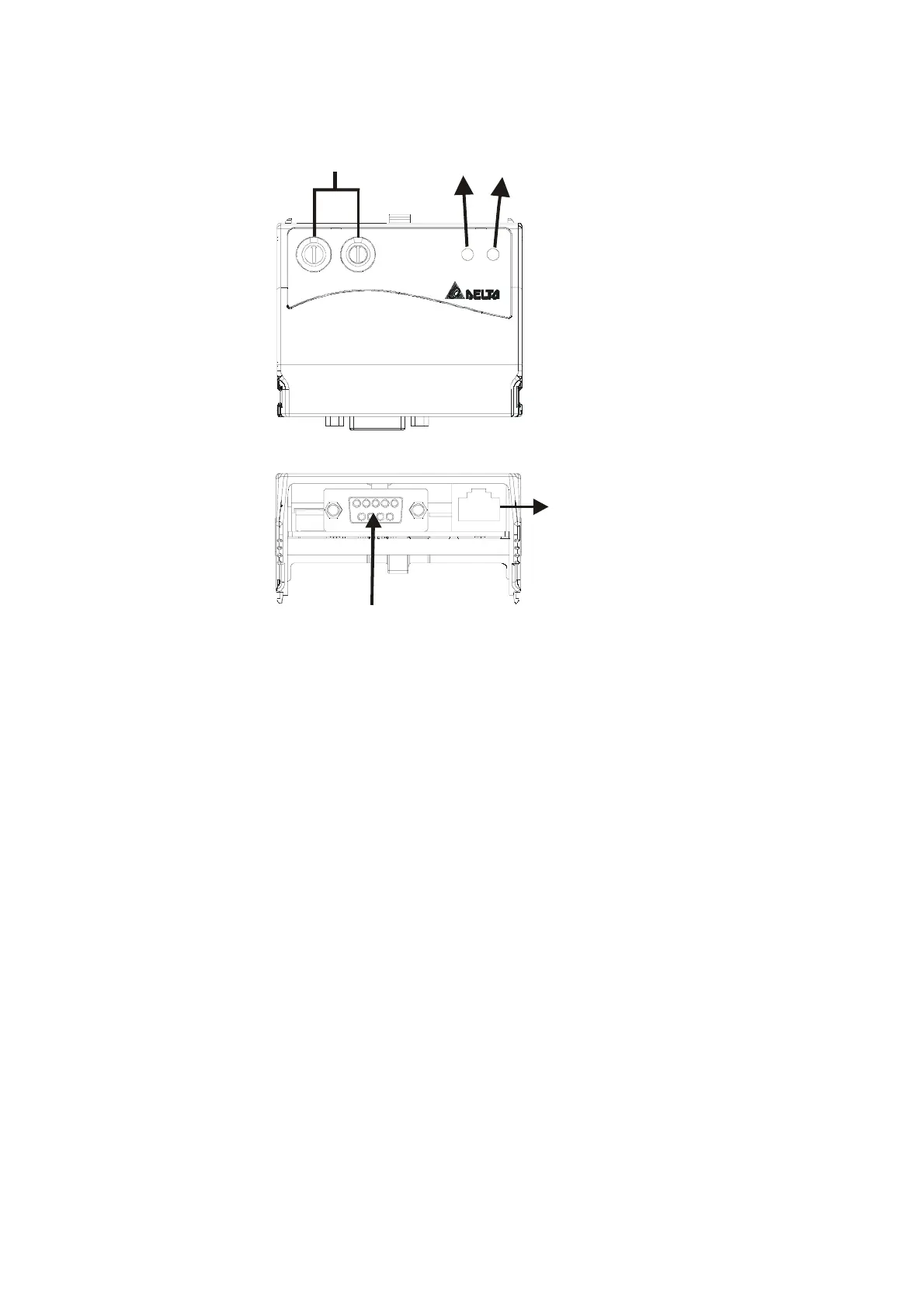
B.10.3.1 Panel Appearance
1: Reserved
2: EV
5: SG+
6: Reserved
7: Reserved
8: Reserved
3: GND
4: S G-
Profibus-DP
Interface (DB9)
RS-485 (RJ45)
ADDH
ADDL
SPNET
CME-PB01
SP LED
NET LEDAddress Switches
1. SP LED: Indicating the connection status between VFD-E and CME-PD01.
2. NET LED: Indicating the connection status between CME-PD01 and PROFIBUS-DP.
3. Address Switches: Setting the address of CME-PD01 on PROFIBUS- DP network.
4. RS-485 Interface (RJ45): Connecting to VFD-E, and supply power to CME-PD01.
5. PROFIBUS-DP Interface (DB9): 9-PIN connector that connects to PROFIBUS-DP
network.
6. Extended Socket: 4-PIN socket that connects to PROFIBUS-DP network.


 To Next Page
 Loading...