Appendix B Accessories
VFD-E Series
Revision August 2006, 01EE, SW--PW V1.03/CTL V2.03 B-23
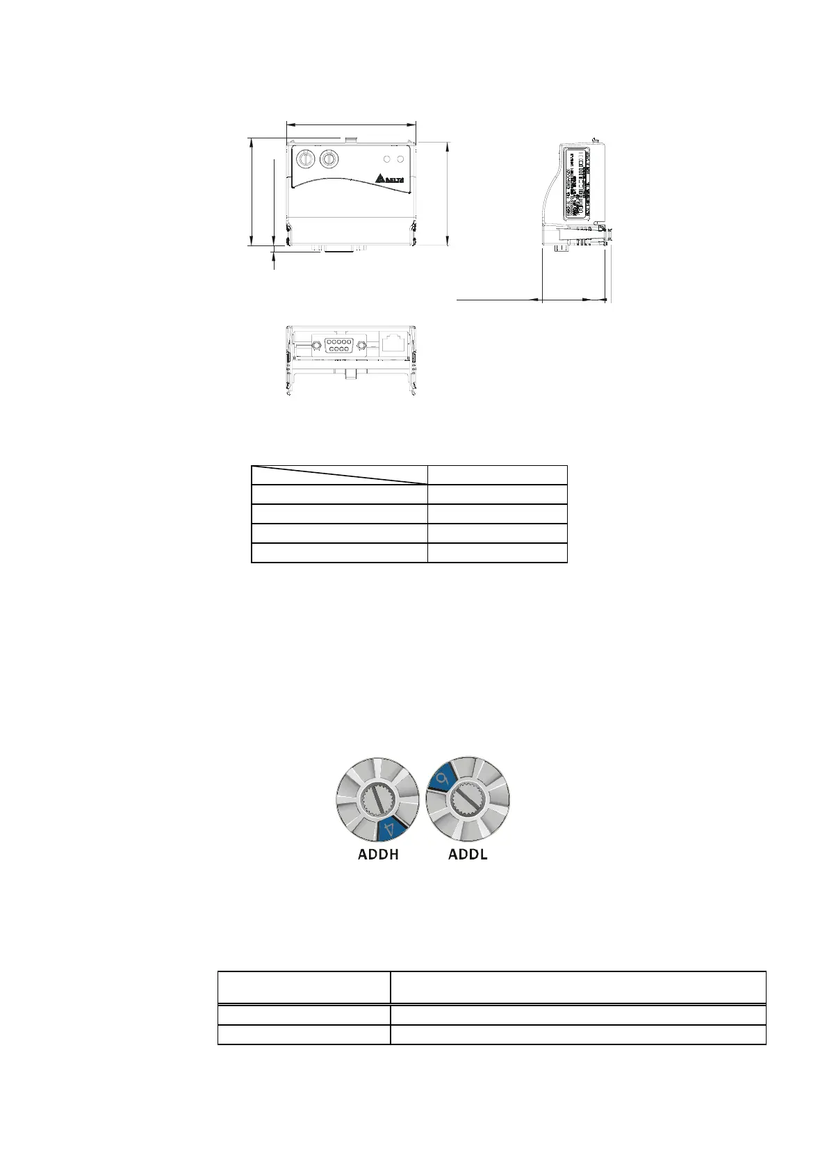
B.10.3.1 Dimensions
57.3 [2.26]
59.7 [2.35]
3.6 [0.14]
72.2 [2.84]
34.8 [1.37]
ADDH ADDL
SPNET
CME-PB01
UNIT: mm(inch)
B.10.3.2 Parameters setting in VFD-E
VFD-E
Baud Rate 9600 Pr.09.01=1
RTU 8, N, 2 Pr.09.03=3
Freq. Source Pr.02.00=4
Command Source Pr.02.01=3
B.10.3.3 Power Supply
The power of CME-PB01 is supplied from VFD-E. Please connect VFD-E to CME-PB01
by using 8 pins RJ-45 cable, which is packed together with CME-PB01. After connection
is completed, CME-PB01 is powered whenever power is applied to VFD-E.
B.10.3.4 PROFIBUS Address
CME-PB01 has two rotary switches for the user to select the PROFIBUS address. The
set value via 2 address switches, ADDH and ADDL, is in HEX format. ADDH sets the
upper 4 bits, and ADDL sets the lower 4 bits of the PROFIBUS address.
Address Meaning
1..0x7D Valid PROFIBUS address
0 or 0x7E..0xFE Invalid PROFIBUS address


 To Next Page
 Loading...