Appendix D How to Use PLC Function
VFD-E Series
D-6 Revision August 2006, 01EE, SW--PW V1.03/CTL V2.03
16-bit binary number, i.e. a word, in each register. It uses two continuous number
of data register to store double words.
& Equipment indication: D0, D1,…,D9,999. The symbol of equipment is D
and the number uses decimal.
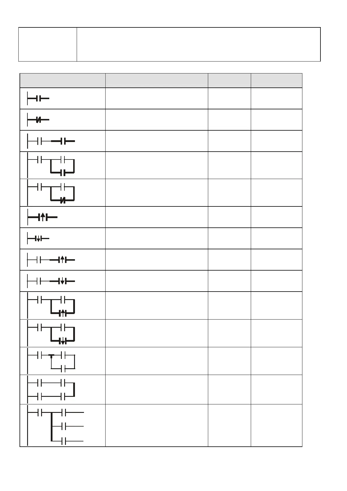
The structure and explanation of ladder diagram:
Ladder Diagram Structure Explanation Command Equipment
Normally open, contact a LD X, Y, M, T, C
Normally closed, contact b LDI X, Y, M, T, C
Serial normally open AND X, Y, M, T, C
Parallel normally open OR X, Y, M, T, C
Parallel normally closed ORI X, Y, M, T, C
Rising-edge trigger switch LDP X, Y, M, T, C
Falling-edge trigger switch LDF X, Y, M, T, C
Rising-edge trigger in serial ANDP X, Y, M, T, C
Falling-edge trigger in serial ANDF X, Y, M, T, C
Rising-edge trigger in parallel ORP X, Y, M, T, C
Falling-edge trigger in parallel ORF X, Y, M, T, C
Block in serial ANB none
Block in parallel ORB none
Multiple output
MPS
MRD
MPP
none


 To Next Page
 Loading...
