Appendix D How to Use PLC Function
VFD-E Series
D-12 Revision August 2006, 01EE, SW--PW V1.03/CTL V2.03
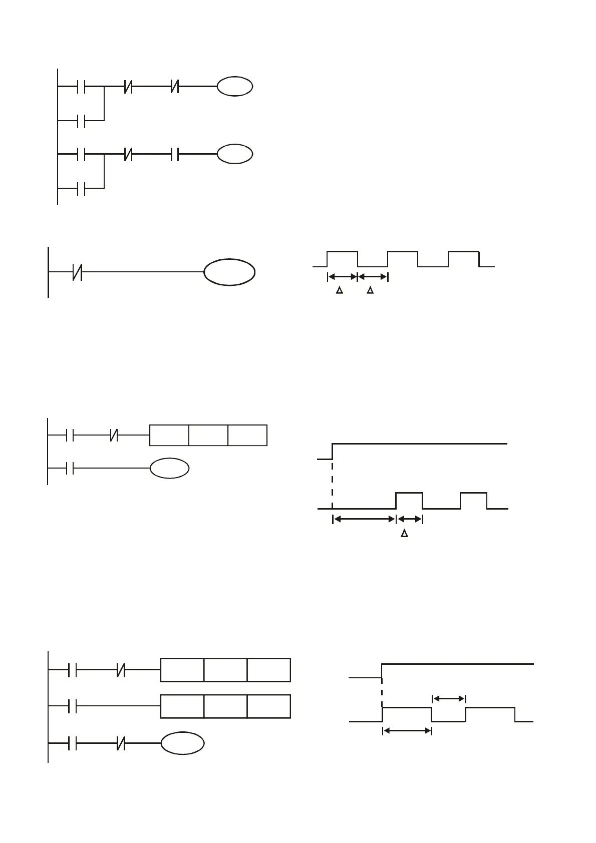
Example 6: Sequential Control
X3
Y1
X1
Y1
X4
Y2
X2
Y2
Y1
Y2
If add normally close contact Y2 into Y1
circuit to be an input for Y1 to do AND
function. (as shown in the left side) Y1 is
an input of Y2 and Y2 can stop Y1 after
acting. In this way, Y1 and Y2 can execute
in sequential.
Example 7: Oscillating Circuit
The period of oscillating circuit is ӔT+ӔT
Y1
Y1
Y1
T T
The figure above is a very simple ladder step diagram. When starting to scan Y1 normally close
contact, Y1 normally close contact is close due to the coil Y1 is OFF. Then it will scan Y1 and the
coil Y1 will be ON and output 1. In the next scan period to scan normally close contact Y1, Y1
normally close contact will be open due to Y1 is ON. Finally, coil Y1 will be OFF. The result of
repeated scan, coil Y will output the vibrating pulse with cycle timeӔT(On)+ӔT(Off).
The vibrating circuitry of cycle time ӔT(On)+ӔT(Off):
T0
X0
TMR
Y1
Y1
T0
Kn
Y1
TTn
X0
The figure above uses timer T0 to control coil Y1 to be ON. After Y1 is ON, timer T0 will be
closed at the next scan period and output Y1. The oscillating circuit will be shown as above. (n
is the setting of timer and it is decimal number. T is the base of timer. (clock period))
Example 8: Blinking Circuit
T2TMR Kn2
T1
X0
TMR
Y1
T2
T1
Kn1
X0 T1
Y1
T
n1
X0
Tn2
*
*


 To Next Page
 Loading...
