Chapter 3 Start Up
VFD-E Series
Revision August 2006, 01EE, SW--PW V1.03/CTL V2.03 2-9
AVI
CI
CM
4~20mA
+10V
5K
3
2
1
Power supply
+10V 20mA
Master Frequency
0 to 10V 47K
Analog Signal Common
E
Main circuit (power) terminals
Control circuit terminals
Shielded leads & Cable
Sw1
NPN
PNP
Factory setting:
NPN Mode
* Don't apply the mains voltage directly
to above terminals.
E
Please refer to Figure 3
for wiring of NPN
mode and PNP
mode.
R(L 1)
S(L2)
T( L3 )
Fuse/NFB(None Fuse Breaker)
SA
OFF
ON
MC
MC
RB
RC
Recommended Circuit
when power supply
is turned OFF by a
fault output
R(L1)
S(L2)
T( L3)
E
Analog Multi-function Output
Te r mi n al
factory setting: Analog freq.
/ current meter
0~10VDC/2mA
U(T1)
V(T 2)
W(T3)
IM
3~
FM
CM
RA
RB
RC
Motor
Factory setting:
Drive is in operation
48V50mA
Multi-function
Photocoulper Output
Analog Signal common
E
E
Refer to Control
Terminal Explanation
MO1
MCM
MI1
MI2
MI3
MI4
MI6
MI5
DCM
+24V
FWD/Stop
REV/Stop
Multi-step 1
Multi-step 2
Multi-step 3
Multi-step 4
Digital Signal Common
Factory
setting
8
1
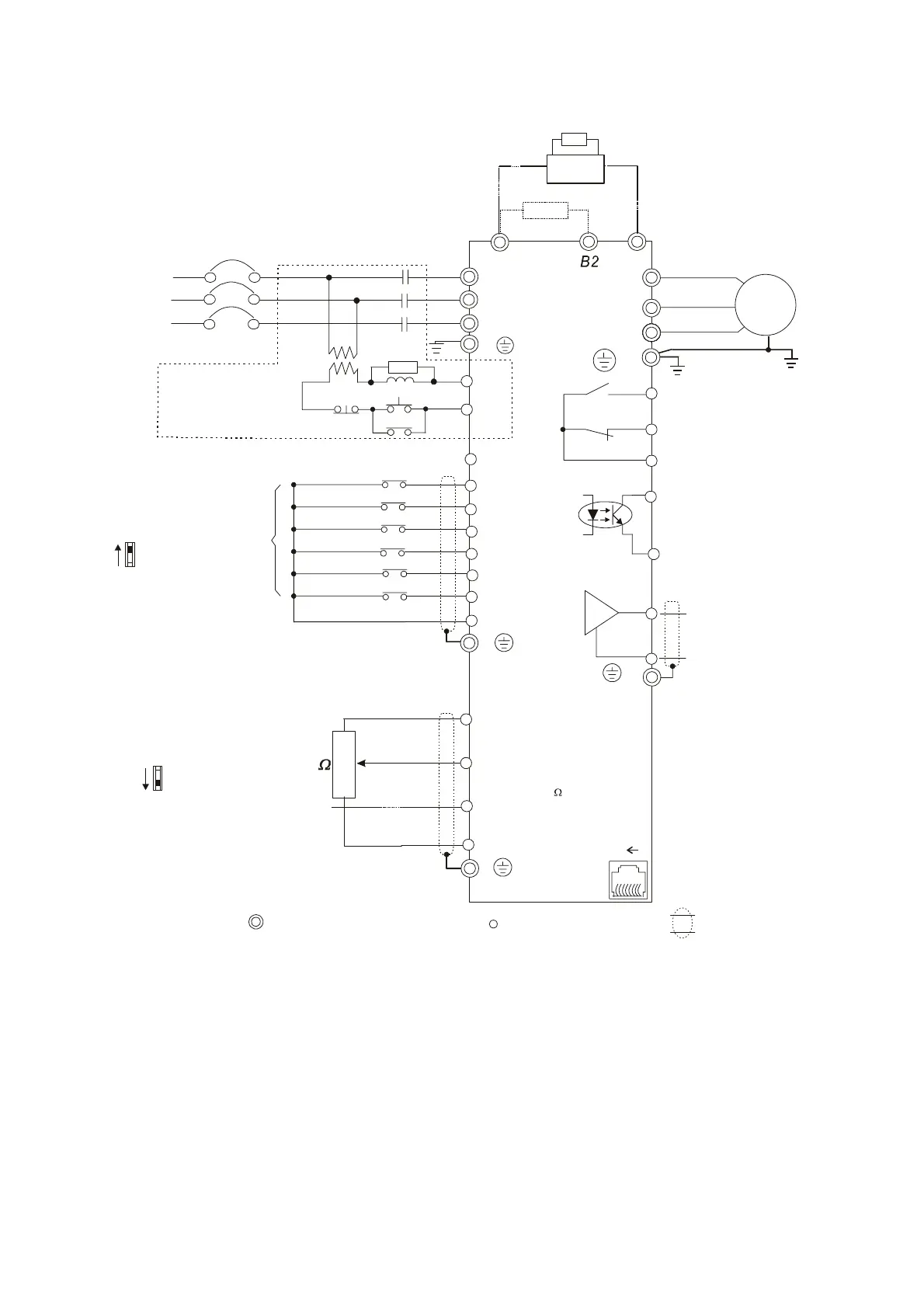
Figure 2 for models of VFD-E Series
VFD007E11A, VFD015E21A, VFD022E21A/23A/43A, VFD037E23A/43A, VFD055E23A/43A,
VFD075E23A/43A, VFD110E43A
+/B1
-
RS-485
Serial interface
1: Reserved
2: EV
5: SG+
6: Reserved
7: Reserved
8: Reserved
3: GND
4: SG-
Sw2
AVI
ACI
Factory setting:
ACI Mode
ACI/AVI switch
When switching to AVI,
it indicates AVI2
Brake
unit
Brake resistor
(optional)
Please use brake unit and/or
brake resistor depending on
type and application
Brake resistor (optional)
* Single-phase models can only use R(L1), S(L2) to be the power terminals.
* Single-phase power cannot be used for 3-phase models.
 Loading...