Appendix D How to Use PLC Function
VFD-E Series
Revision August 2006, 01EE, SW--PW V1.03/CTL V2.03 D-45
Explanations:
1. Refer to specification for usage range.
2. S
1
S
2
D. Performs the addition on BIN data S
1
and the BIN data S
2
, and stores the
addition result into the device D.
3. The most significant bit are the symbolic bit 0 and 1. 0 indicates positive and 1 indicates
negative. All calculation are algebraically processed, i.e. 3 (-9) -6.
4. Flag changes of binary addition
16-bit command:
A. If the operation result is “0”, then the Zero flag, M1020 is set to ON.
B. If the operation result exceeds -32,768, the borrow flag, M1021 is set to ON.
C. If the operation result exceeds 32,767, the carry flag, M1022 is set to ON.
Program Example 1:
16-bit command:
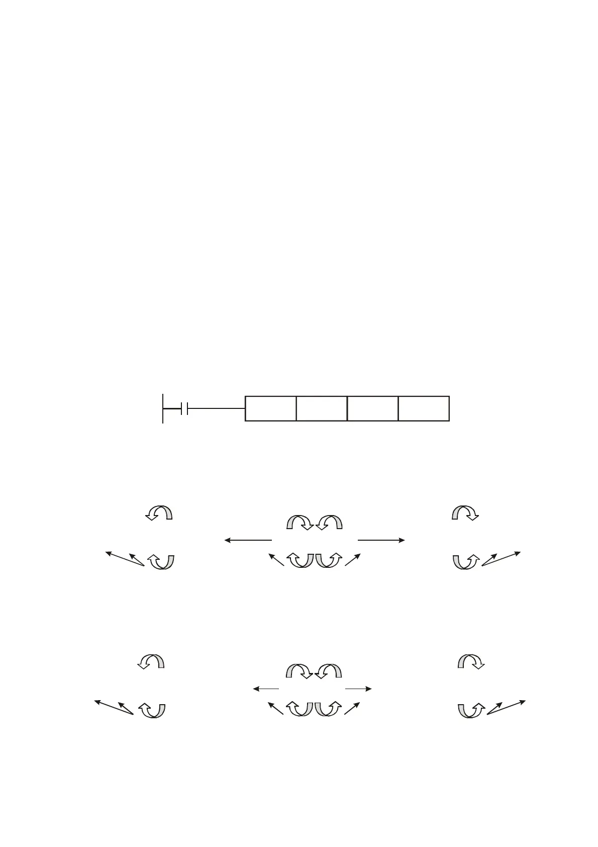
When X0 is ON, the data contained within the augend D0 and addend D10 is combined and the total
is stored in the result device D20.
X0
ADD D0 D10 D20
Remarks:
Flag operations:
-2 -1 0 -32,768%%% %%-1 0 1 32,767 0 1 2%%%
-2 -1 0 -2,147,483,648%%% %%-1 0 1 2,147,483,647 0 1 2%%%
16-bit command: Zero flag
Zero flag
Zero flag
Borrow flag
the most significant bit
becomes “1” (negative)
32-bit command: Zero flag
Zero flag
Zero flag
the most significant bit
becomes “0” (positive)
Carry flag
Borrow flag
the most significant bit
becomes “1” (negative)
the most significant bit
becomes “0” (positive)
Carry flag


 To Next Page
 Loading...
