Appendix D How to Use PLC Function
VFD-E Series
Revision August 2006, 01EE, SW--PW V1.03/CTL V2.03 D-49
Explanations:
1. If the command is not the pulse execution command, “1” is added to the value of
destination device D on every execution of the command whenever INC command is
scanned for each cycle. This command is usually pulse execution (INCP).
2. In 16-bit command, when +32,767 is reached, “1” is added and it will write a value of –
32,768 to the destination device. In 32-bit command, when +2,147,483,647 is reached,
“1” is added and it will write a value of -2,147,483,648 to the destination device.
3. Flag M1020~M1022 won’t be influenced by the operation result of this command.
Program Example:
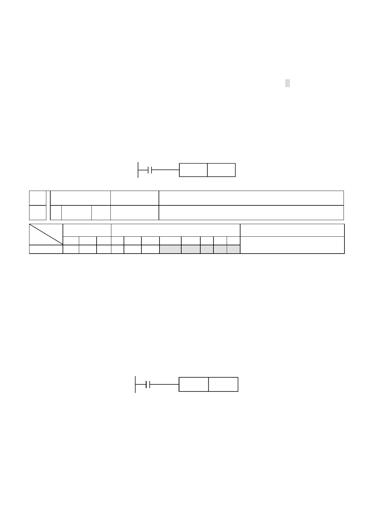
When X0 is ON, the content of D0 will perform the addition of 1.
X0
INCP D0
API Mnemonic Operands Function
25 DEC P D Decrement
Bit Devices Word devices Program Steps
Type
OP
X Y M K H KnX KnY KnM T C D
D * * * * *
DEC, DECP: 3 steps
Operands:
D: Destination
Explanations:
1. If operand D use with device F, it is only available in 16-bit command.
2. In 16-bit command, when –32,768 is reached, “1” is subtracted and it will write a value of
+32,767 to the destination device. In 32-bit command, when -2,147,483,648 is reached,
“1” is subtracted and it will write a value of +2,147,483,647 to the destination device.
3. Flag M1020~M1022 won’t be influenced by the operation result of this command.
Program Example:
When X0 is ON, the content of D0 will perform the subtraction of 1.
X0
DECP D0


 To Next Page
 Loading...
