Chapter 5 Parameters
VFD-E Series
5-24 Revision August 2006, 01EE, SW--PW V1.03/CTL V2.03
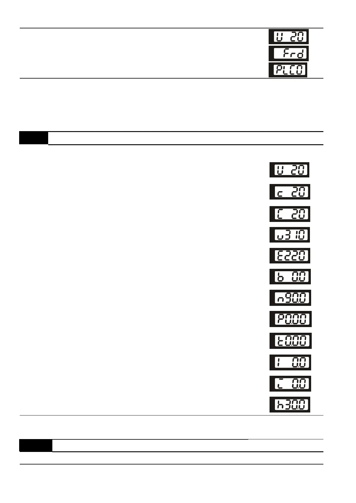
3 Display the content of user-defined unit (Uxxx)
4 FWD/REV command
5 PLCx (PLC selections: PLC0/PLC1/PLC2)
This parameter determines the start-up display page after power is applied to the drive.
For setting 5, PLC0: disable, PLC1: run PLC, PLC2: read/write PLC programs into AC motor
drive.
00.04 aContent of Multi-function Display
Factory Setting: 0
Settings 0 Display the content of user-defined unit (Uxxx)
1
Display the counter value which counts the number of
pulses on TRG terminal
2 Display PLC D1043 value (C)
3
Display the actual DC BUS voltage in VDC of the AC
motor drive
4
Display the output voltage in VAC of terminals U/T1,
V/T2, W/T3 to the motor.
5 Display PID analog feedback signal value in %
6
Display the power factor angle in º of terminals U/T1,
V/T2, W/T3 to the motor
7
Display the output power in kW of terminals U, V and W
to the motor.
8
Display the estimated value of torque in Nm as it relates
to current.
9
Display the signal of AVI analog input terminal (V).
10
Display the signal of ACI analog input terminal (mA)or
display the signal of AVI2 analog input terminal-(V).
11
Display the temperature of IGBT (h) in C
00.05 aUser Defined Coefficient K Unit: 0. 1
Settings 0. 1 to d 160.0 Factory Setting: 1.0
 Loading...