Chapter 5 Parameters
VFD-E Series
5-48 Revision August 2006, 01EE, SW--PW V1.03/CTL V2.03
Bit2: MO2/RA2 Status
Bit3: MO3/RA3 Status
Bit4: MO4/RA4 Status
Bit5: MO5/RA5 Status
Bit6: MO6/RA6 Status
Bit7: MO7/RA7 Status
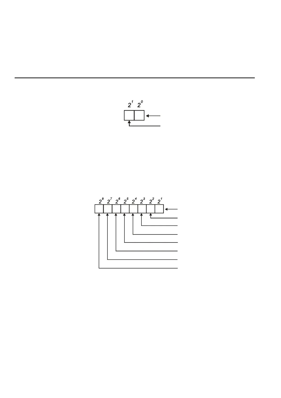
For standard AC motor drive (without extension card), the multi-function output terminals are
falling-edge triggered and Pr.03.13 will display 3 (11) for no action.
1 0
Weights
Bit
0=Active
1=Off
Relay 1
MO1
For Example:
If Pr.03.13 displays 2, it means Relay 1 is active.
The display value 2 =bit 1 X 2
1
When extension card is installed, the number of the multi-function output terminals will
increase according to the extension card. The maximum number of the multi-function output
terminals is shown as follows.
1 0
Weights
Bit
Relay 1
MO1
3 25 47 6
MO2/RA2
MO3/RA3
MO4/RA4
MO5/RA5
MO6/RA6
MO7/RA7
0=Active
1=Off


 To Next Page
 Loading...