Operation with LED-lamps:
Preconditions (not included in shipment)
2 or 4 free 1-10 V-interfaces (1 or 2 L-ports) at ProfiLux
LED-lamps with common anode (+) which can be controlled via PWM (Open Drain)
power supply with adequate voltage and power
Connection and operation
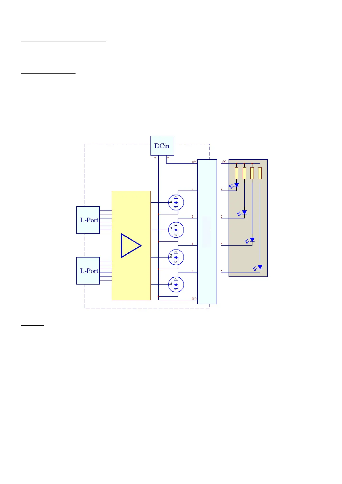
To the DC-socket (DCin) a suited power supply unit is connected. Alternatively pins 1 (+) and 6 (-) can be used for the power supply.
The supplied control lines (Western cables) are at one end connected to the corresponding sockets of LEDControl4 (L1L2, L3L4), on the other
end to free sockets with 1-10V-interface (e.g. L1L2 and L3L4) of ProfiLux.
The LED-lamp is connected via the supplied screw-type terminal to (PWM-OUT), here Plus applies permanently, Minus is pulsed with PWM.
Several LED-lamp manufacturers offer suited adapter cables for connecting their lamps to LEDControl4.
Please note that pin 6 of the LEDControl4 V2 socket remains free if the plug has 5 pins!
Block diagram for connection of a LED-lamp:
Example 1:
Connection of two light stripes red and white with a nominal voltage of 24V.
In this case a power supply unit with 24V (with DC-plug, plus pole inside) is needed. The plus line of both LED-stripes must be connected to the
PWM-OUT connection leftmost (Pin 1). The minus line of the white LED-stripe must be connected to the PWM-channel 4 (Pin 2) and the minus
line of the red LED-stripe must be connected to the PWM-channel 3 (Pin 3). Since only the first two PWM-channels (Pin 2 & Pin 3) are used,
only the right L-port (L3L4) of LEDControl4 has to be connected with a free L-port at ProfiLux, the other L-port is unused and can left free. If
only white flashes shall be generated, LEDControl4 must be programmed to „Flash at channel 1“ in order that the other channel with the red
LEDs doesn’t generate a flash.
Example 2:
Connection of a light stick or light stripe with 4 colors (red, green, blue and white). The light stick resp. light stripe has a nominal voltage of 12
V and a common anode (+) for all colors.
In this case a power supply unit with 12 V (with DC-plug, plus pole inside) is required. The common plus line must be connected to the PWM-
OUT connection leftmost (Pin 1). The colors white, blue, green and red are connected with Pin 2 to Pin 5. It is recommended to connect the
white LEDs to PWM-channel 4 (Pin 2), since here a flash can be generated. If you like to have white-blue flashes, then connect the blue LEDs
with PWM-channel 3 (Pin 3) and program in ProfiLuxControl „Flash at channel 1 & channel 2“. The connection rightmost (Pin 6) remains free.
 Loading...